
How to read a factory wiring diagram for the FD3S engine bay
An FD3S engine-bay wiring diagram can look like a maze of thin lines, Japanese abbreviations and connector symbols. It becomes far easier to follow once you treat it as a map of circuits rather than a picture of where each wire sits in the car.
For Australian owners, this skill is useful when diagnosing a hard-starting 13B-REW, checking an imported Series 6, repairing corrosion near the battery or preparing a car for a roadworthy inspection. A multimeter, the correct factory manual and a disciplined method will usually reveal more than randomly replacing sensors.
| Diagram feature | What it tells you | Useful checking method |
|---|---|---|
| Wire colour code | The insulation colour and tracer | Compare with the connector and test continuity |
| Connector ID | Which plug or junction is shown | Locate the matching plug in the engine bay |
| Ground symbol | Where current returns to the chassis or engine | Check resistance and voltage drop |
| Fuse or relay | Circuit protection and switched power | Test both sides under load |
| Splice or junction | A shared feed or signal branch | Check whether several components lose power together |
| ECU pin number | The control-unit terminal involved | Back-probe carefully with the ECU connected |
Start with the diagram’s layout
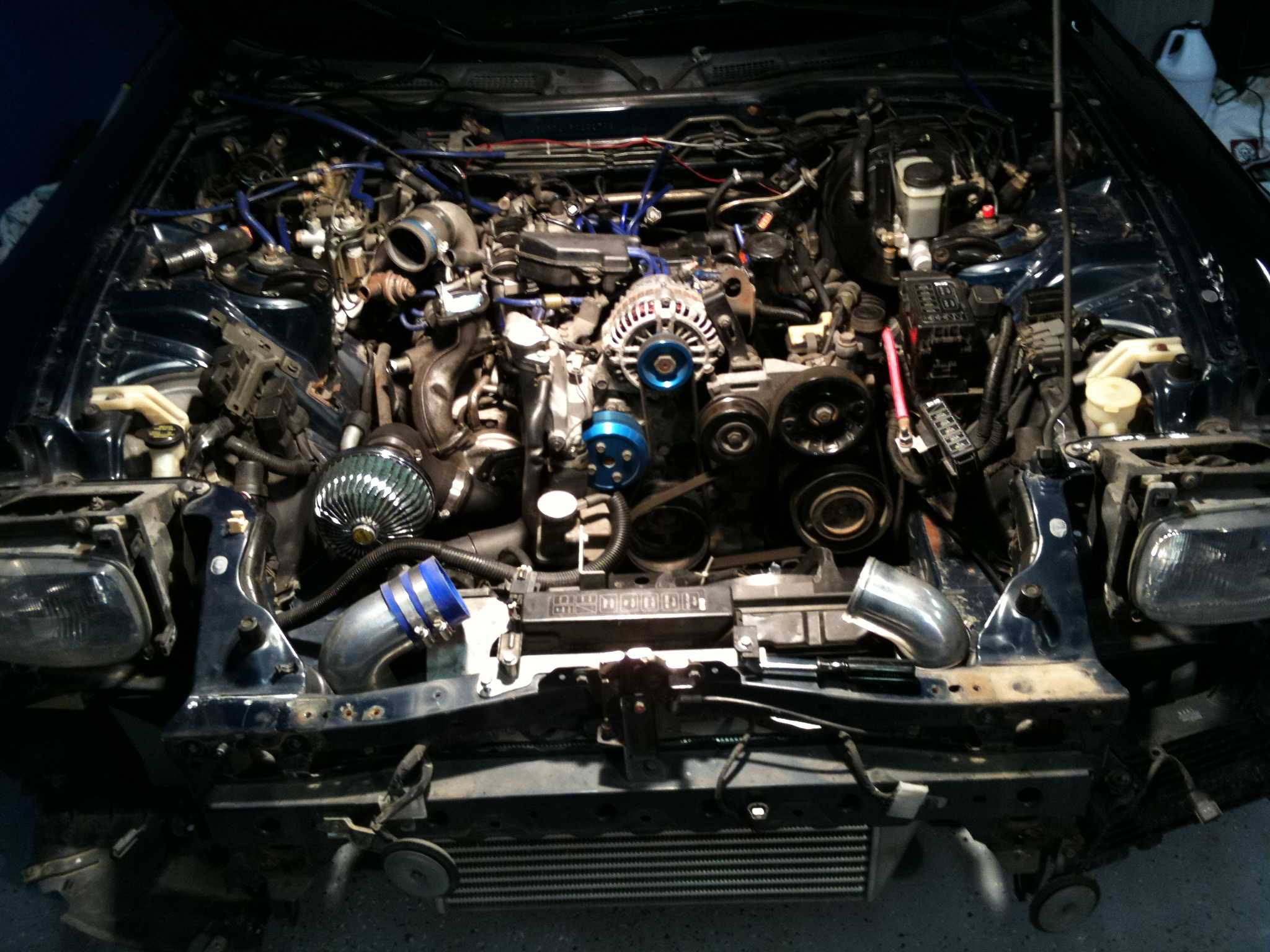
Factory diagrams commonly divide the engine bay into power supply, ignition, fuel injection, emissions control, cooling and engine-management circuits. Begin by finding the battery, main fuse box, ignition switch and ECU. These are the major reference points that explain where power enters and how it is distributed.
Do not assume that a line drawn near a component is physically routed beside it. A wiring schematic shows electrical relationships, not the exact path through the loom. Connector pages, harness illustrations and grounding-point diagrams are needed to translate the schematic into the real FD3S bay.
Download or print the relevant pages from a reliable factory reference library, then mark the circuit you are investigating. Keep the car’s model year and Series in mind, as Japanese-market FD wiring can differ in ECU, emissions and sensor arrangements.
Learn the symbols and colour codes
A solid line normally represents a conductor, while a junction dot indicates that wires are electrically joined. Lines crossing without a dot may simply pass over one another. A rectangle may identify a relay, resistor, fuse or control unit, so use the legend instead of guessing from its shape.
Wire colours are often abbreviated. Black may indicate a ground-related wire, while combinations such as B/W or R/B usually mean a base colour with a tracer. The exact convention varies between manuals, and faded insulation can make a white wire appear grey in an engine bay exposed to heat and oil.
Treat colour as a guide rather than proof. Confirm the terminal by connector position, wire continuity and voltage. This matters when working on an imported RX-7 that has had an alarm, stereo, boost controller or aftermarket immobiliser fitted by a previous owner.
Trace power before chasing signals
Most diagnostic work should follow the current path from the battery towards the component. Check the main fuse, ignition-switched supply, relay output and connector terminal before testing the sensor itself. If several unrelated components fail together, look for a common feed or earth rather than assuming multiple parts broke simultaneously.
The FD3S relies on dependable grounds around the engine, chassis and intake or control-system wiring. A ground can look clean while producing excessive voltage drop under load. Place one multimeter probe at the suspected ground and the other at the battery negative terminal while cranking or operating the relevant circuit.
Heat, moisture and previous repairs are practical concerns in Australia. A car used in Brisbane traffic may suffer more under-bonnet heat, while coastal areas such as Sydney or Perth can expose terminals and earth points to humidity and salt. A small voltage-drop test can identify problems that a simple continuity beep misses.
Follow connectors and splices carefully
Connector labels such as ECU plugs, sensor plugs and intermediate couplers are the bridge between the schematic and the vehicle. Locate the connector on the diagram, identify its pin numbering direction, then verify whether you are viewing the wire side or terminal side. Reversed orientation is a common cause of incorrect diagnosis.
Splices are especially important in circuits for injectors, ignition coils, solenoids and sensor supplies. One damaged splice can disable several systems while leaving the rest of the harness apparently intact. Gently inspect repaired sections for crimp joins, solder covered in brittle tape and insulation damaged by turbocharger heat.
Keep a written record of connector numbers, measured voltage and wire colours. This is more useful than relying on memory, particularly when a car has been modified over several years. A simple annotated copy of the schematic can save an auto electrician in Melbourne or a home mechanic in Newcastle hours of repeated testing.
Separate factory wiring from modifications
Before diagnosing the ECU, identify anything that is not shown in the original diagram. Common additions include wideband oxygen sensors, fuel pumps, electric fans, boost solenoids, piggyback controllers and aftermarket alarm systems. Trace each modification to its fuse, relay and earth, then note whether it interrupts a factory wire or merely connects in parallel.
Use the production year and equipment specification to avoid applying the wrong circuit. The Australian market received many imported vehicles with different histories, and an FD3S from Japan may have a replacement engine loom or a different ECU from the chassis documentation. When preserving records from different model years, a useful archiving older information approach is to label each scan with its source and revision.
Never pierce a wire unnecessarily, and avoid probing ECU terminals with oversized test leads. Back-probe from the connector seal, use fused test equipment and disconnect the battery before repairing a damaged section. Proper heat-shrink and sealed crimps are preferable to household electrical tape in the engine bay.
Use the schematic for diagnosis and tuning
A wiring diagram is valuable when checking engine-management changes, but it should not replace a measured baseline. Confirm battery voltage, ignition supply, injector power, sensor grounds and ECU grounds before adjusting fuel or ignition maps. A wiring fault can imitate poor calibration, boost-control trouble or a failing rotary ignition system.
Transmission and engine wiring can also overlap through neutral, clutch, reverse-light and vehicle-speed signals. If you are investigating drivability around gear changes, compare the relevant terminals with a five-speed reference rather than assuming every fault is inside the gearbox.
For cars running an aftermarket controller, document every altered input and output before making changes. The PowerFC tuning guide is a useful companion when tracing ECU-related connections, especially where sensor signals, auxiliary outputs or boost-control wiring differ from the factory arrangement. Keep the original circuit intact wherever possible so the car remains diagnosable.
Once the circuit is understood, test it in a fixed order: visual inspection, fuse check, power supply, ground quality, continuity, signal behaviour and component operation. Save your annotated FD3S diagrams with the vehicle’s Series, ECU type and modifications. That small reference pack can make the next fault easier to solve, whether the RX-7 is in a Sydney garage, a Queensland workshop or heading to a NSW pink-slip inspection. Start with one circuit, record every measurement and use the factory schematic as your map.