
Welding a Turbo Manifold for a Rotary Engine
A turbo manifold for a Mazda rotary engine must survive extreme exhaust temperature, vibration and repeated heat cycles. The compact 13B engine bay leaves little room for graceful bends, so a successful design depends on accurate measurements as much as welding skill.
Before cutting stainless or mild-steel tube, identify the engine version, exhaust-port pattern, turbocharger position and wastegate arrangement. Factory dimensions and related specifications are available through OEM information, which can help prevent errors caused by mixing Series 4, Series 5 or 20B components.
This is a fabrication project, not simply a matter of joining pipes. Poor alignment can create exhaust leaks, warped flanges, turbocharger stress or a wastegate that cannot control boost. Work slowly, test-fit everything and treat the finished manifold as a structural, high-temperature component.
Planning the Rotary Turbo Layout
Start by deciding whether the turbocharger will sit high or low, forward or near the firewall, and whether the manifold will be a log, cast-style replacement or tubular equal-length design. A log manifold is compact and generally easier to package, while a tubular arrangement can improve flow and turbine response when runner length and collector geometry are carefully controlled.
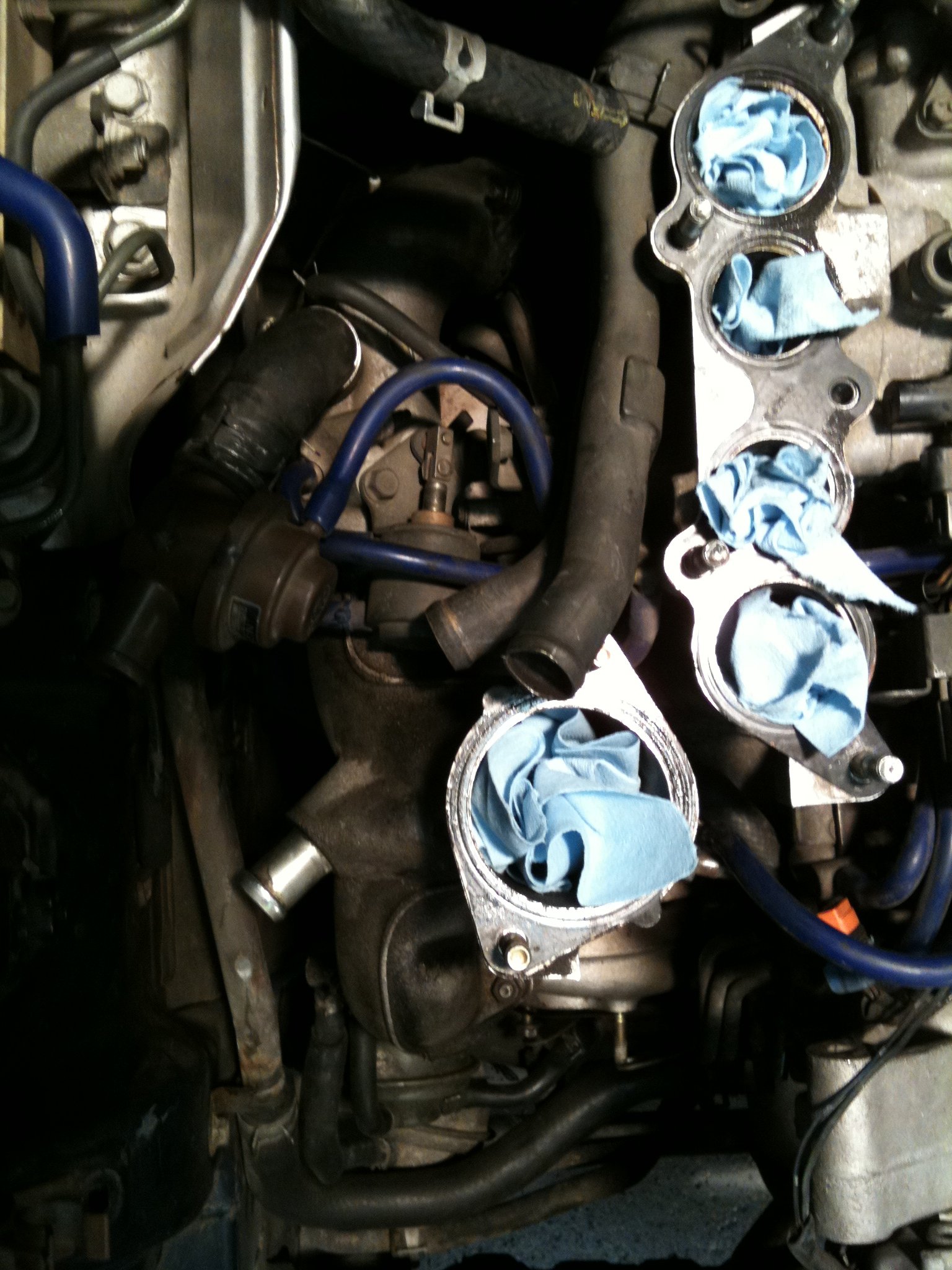
The rotary exhaust ports discharge pulses differently from a piston engine, and the large exhaust window can make port matching important. Review rotary basics before choosing runner diameter, flange thickness or collector size. For many street 13B builds, moderate primary tubing gives a useful balance between velocity, clearance and peak power.
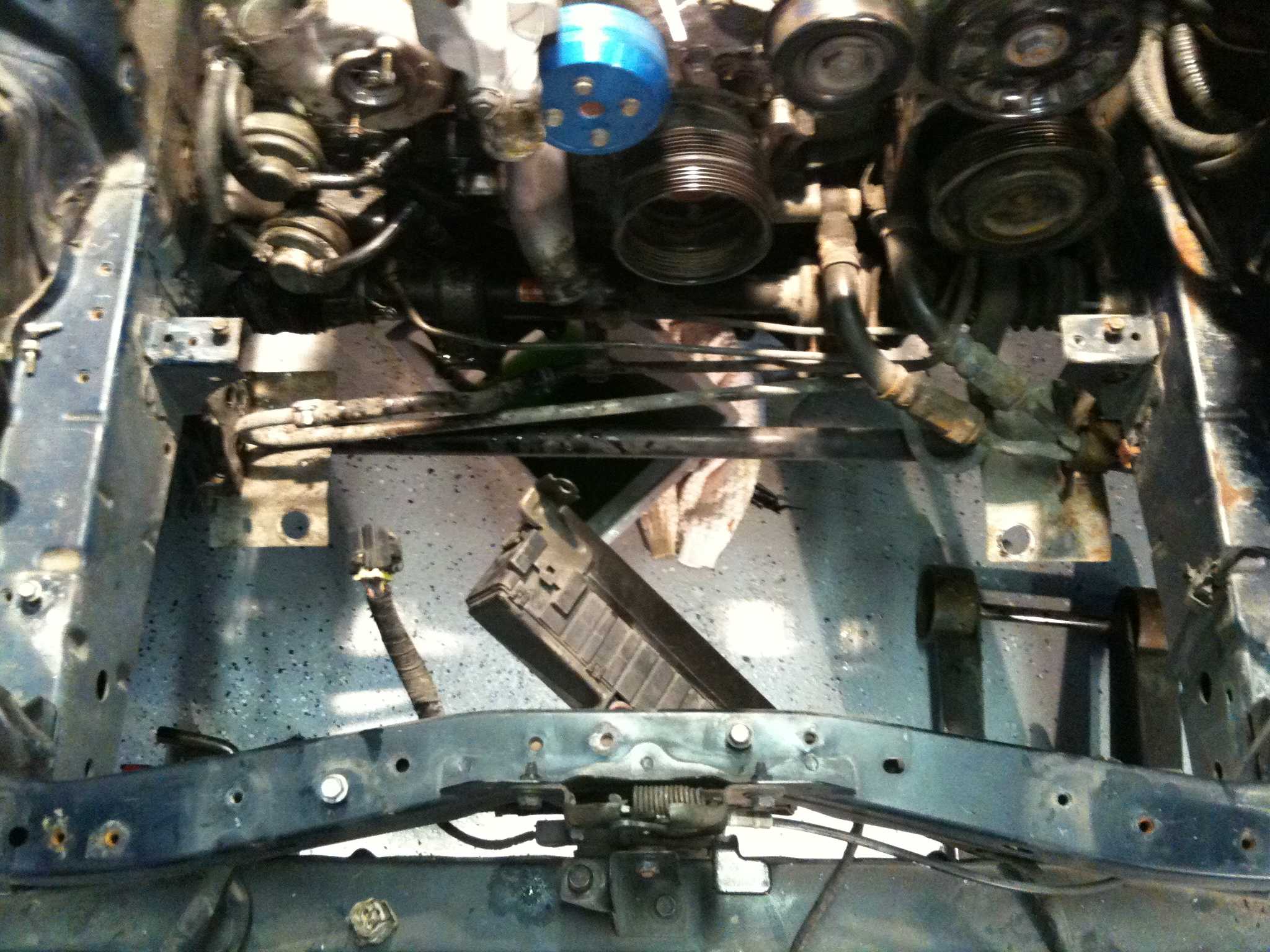
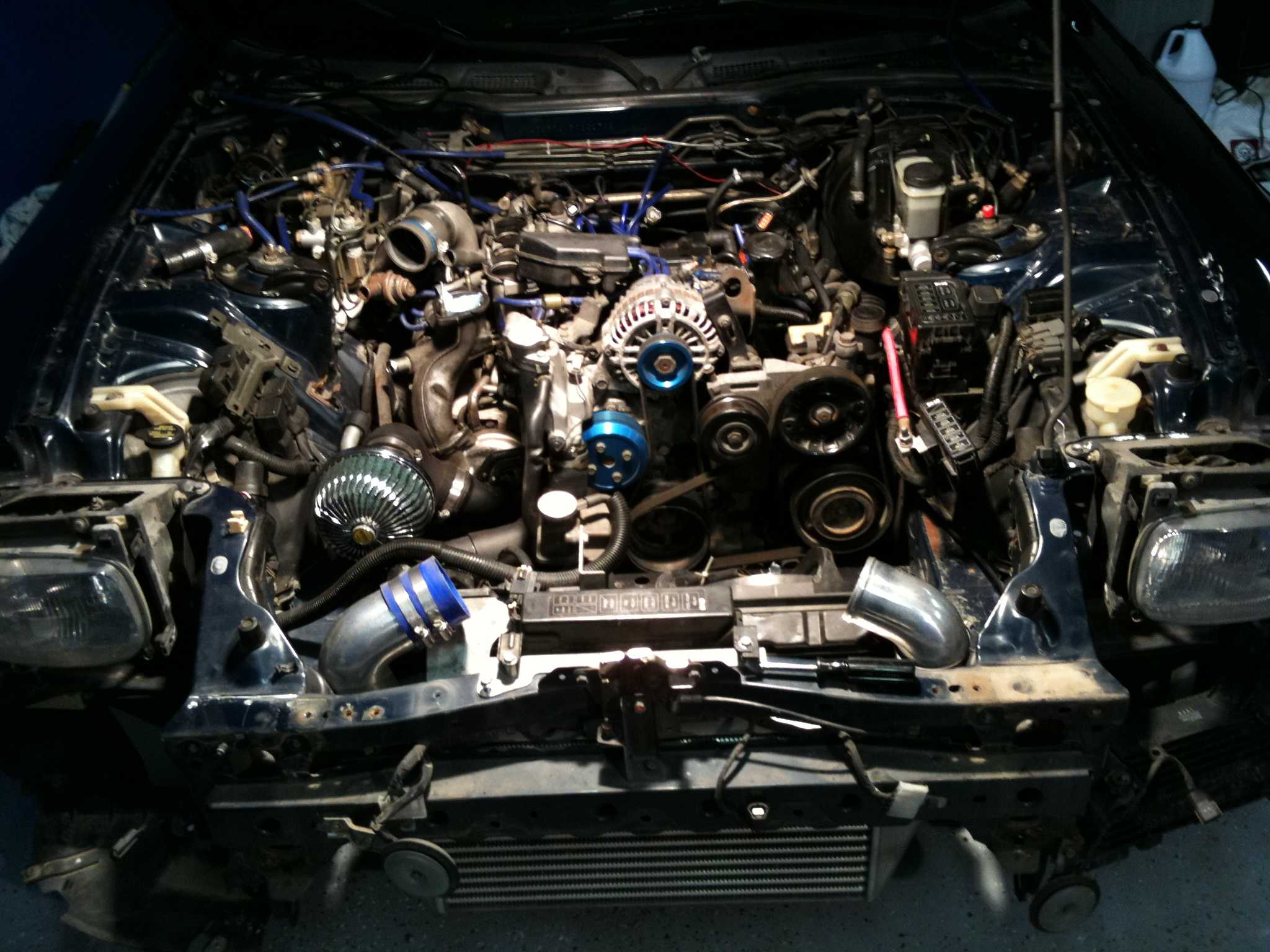
Make a cardboard or aluminium mock-up before ordering materials. Include the turbo flange, downpipe, oil drain, intake pipe, water lines, ignition components and bonnet clearance. In Sydney or Melbourne, where modified RX-7s may need to pass an engineering inspection, a tidy and serviceable layout is easier to document than a tightly packed design that blocks access to sensors or fasteners.
Choosing Materials and Preparing Joints
304 stainless steel is common for custom turbo manifolds because it resists corrosion and is widely available from Australian exhaust suppliers. 321 stainless tolerates heat cycling better, although it costs more and may be harder to source in small quantities. Mild steel is inexpensive and easy to weld, but it needs coating or paint protection and may rust quickly in coastal areas such as Brisbane, Newcastle or Perth.
Use a substantial flange, generally around 10–12 mm for a turbo mounting plate, and check that it is flat before welding. Laser-cut flanges often need machining or careful dressing. Deburr every tube, remove mill scale and degrease the joint. A small gap at a butt joint can help penetration, but inconsistent gaps encourage distortion and internal steps.
A practical way to organise reference material is to keep technical drawings separate from general browsing, including additional visual material that may help with workshop layout or presentation. It should not replace verified dimensions, weld procedure information or manufacturer data.
Tack Welding and TIG Technique
TIG welding is usually the best choice for a thin-wall stainless turbo manifold because it provides controlled heat input and clean internal penetration. Use a gas lens, a sharp tungsten and high-purity argon. Back-purge the inside of stainless tubes with argon so the weld root does not form heavy sugaring that can break away and damage the turbine wheel.
Clamp the assembly to a thick fixture or temporary jig, then tack each joint at several evenly spaced points. Alternate sides and allow the manifold to cool between passes. Do not fully weld one runner before checking the other joints, because accumulated shrinkage can pull the turbo flange out of alignment.
A moderate travel speed and short arc help control the puddle. Filler rod should suit the base metal, such as ER308L for many 304 stainless joints. Keep the torch angle consistent, avoid excessive reinforcement and inspect the inside wherever possible. If the manifold is mild steel, use suitable filler and protect the completed surface against corrosion.
Managing Heat, Bracing and Cracking
The turbocharger adds significant weight to the manifold, and vibration can turn a small weld defect into a major crack. Add a brace from the turbocharger or collector to a strong engine or gearbox mounting point, allowing for movement without locking the assembly rigidly to the chassis. A brace should support weight rather than force the manifold into position.
Plan a flexible connection after the turbo outlet. A quality bellows or flex section in the downpipe helps isolate the manifold from exhaust-system movement. Avoid placing a flex joint where it will sag onto the ground or sit beside a brake line. Heat shielding and reflective barriers are especially valuable during Australian summer driving, when ambient temperatures in Adelaide, Perth and inland regions increase under-bonnet heat.
Do not assume a beautiful external weld proves the design is finished. Pressure-test the manifold with low-pressure air and soapy water, check flange flatness after cooling and inspect for hairline cracks after the first few heat cycles. Recheck turbo oil and water connections, then retighten fasteners using a controlled sequence.
Testing, Compliance and Final Choices
Wastegate placement deserves careful attention. The gate should receive a strong, direct view of exhaust flow rather than relying on a narrow branch at the end of a runner. Its outlet must be directed safely, and an external screamer pipe may create noise and emissions problems. Australian road rules vary by state, but modifications that affect emissions, noise, engine power or structural safety can require inspection or certification; NSW owners may need the Vehicle Safety Compliance Certification Scheme, while Queensland uses modification-plate requirements for relevant changes.
A dyno session should begin with conservative boost and suitable engine-management calibration. Monitor exhaust gas temperature, air-fuel ratio, boost control and signs of detonation. The manifold design cannot compensate for poor fuel delivery or an unsuitable ignition map. Research into housing materials, including the Nikasil and iron-liner debate, also reinforces the importance of matching parts to the engine’s intended use rather than chasing one isolated specification.
| Manifold approach | Strengths | Limitations | Suitable use |
|---|---|---|---|
| Mild-steel log | Affordable, compact and easy to repair | Heavier and more prone to corrosion | Budget street builds |
| 304 stainless tubular | Good corrosion resistance and attractive finish | More distortion and cracking risk if poorly welded | Carefully fabricated street and track cars |
| 321 stainless tubular | Strong heat-cycle performance | Higher cost and less local availability | High-temperature or competition builds |
| Cast-style manifold | Excellent durability and repeatable fit | Less freedom for custom turbo placement | Reliable packaged conversions |
Keep a record of material grade, flange thickness, filler rod, purge method and final measurements. That documentation can support future repairs, tuning decisions and any engineering discussion. For readers who also maintain unrelated lifestyle bookmarks, a separate lifestyle resource can remain outside the technical workshop reference folder.
Build the manifold around measured clearances, controlled welding and realistic road use. Gather the correct rotary documentation, fabricate a temporary mock-up, use a qualified welder when needed and verify the finished installation before increasing boost. A carefully planned turbo system will reward the effort with better reliability, easier servicing and a far lower chance of an expensive exhaust-side failure.