
Rotary Engine Rebuild Sequence From Teardown to Assembly
A rotary engine rebuild rewards patience, accurate measurement and disciplined organisation. The basic process applies to Mazda 12A, 13B and 20B engines, although housing count, eccentric-shaft arrangement and component availability change the workload. Treat the job as a measured restoration rather than a quick gasket replacement.
Before opening the engine, gather factory specifications, a clean workbench, seal drivers, micrometers, a dial indicator and reliable torque tools. The OEM specifications available through TurboRX7 can help establish the correct clearances, torque values and assembly details for the particular engine code.
Australian owners also need to plan around local conditions. A turbo rotary used in Sydney traffic, Brisbane humidity or Adelaide summer heat needs strong cooling and careful oil control. Modified vehicles may require inspection or engineering certification under state-based roadworthiness and modification rules, so retain receipts, measurements and build records from the beginning.
Prepare The Engine And Workspace
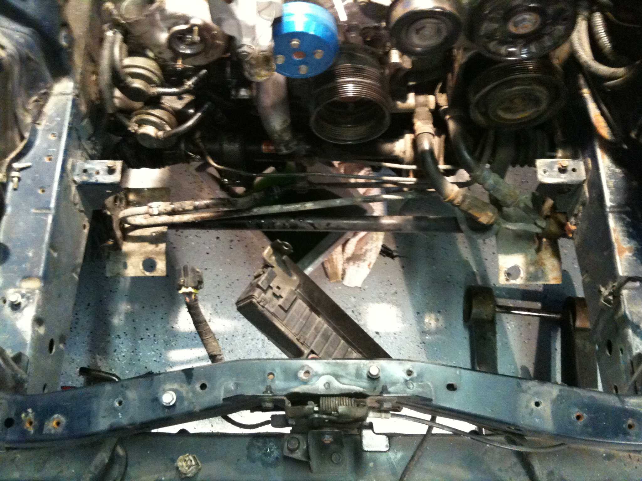
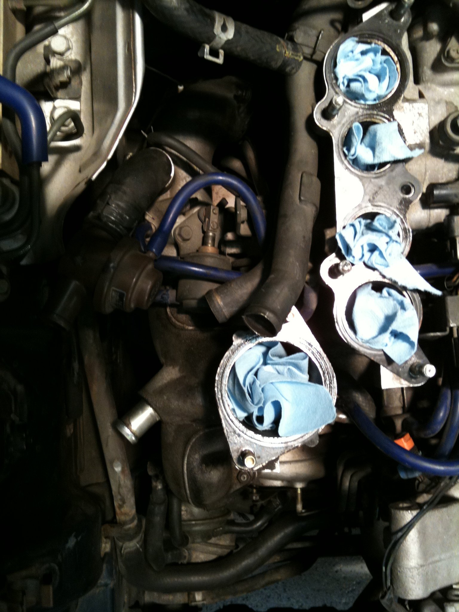
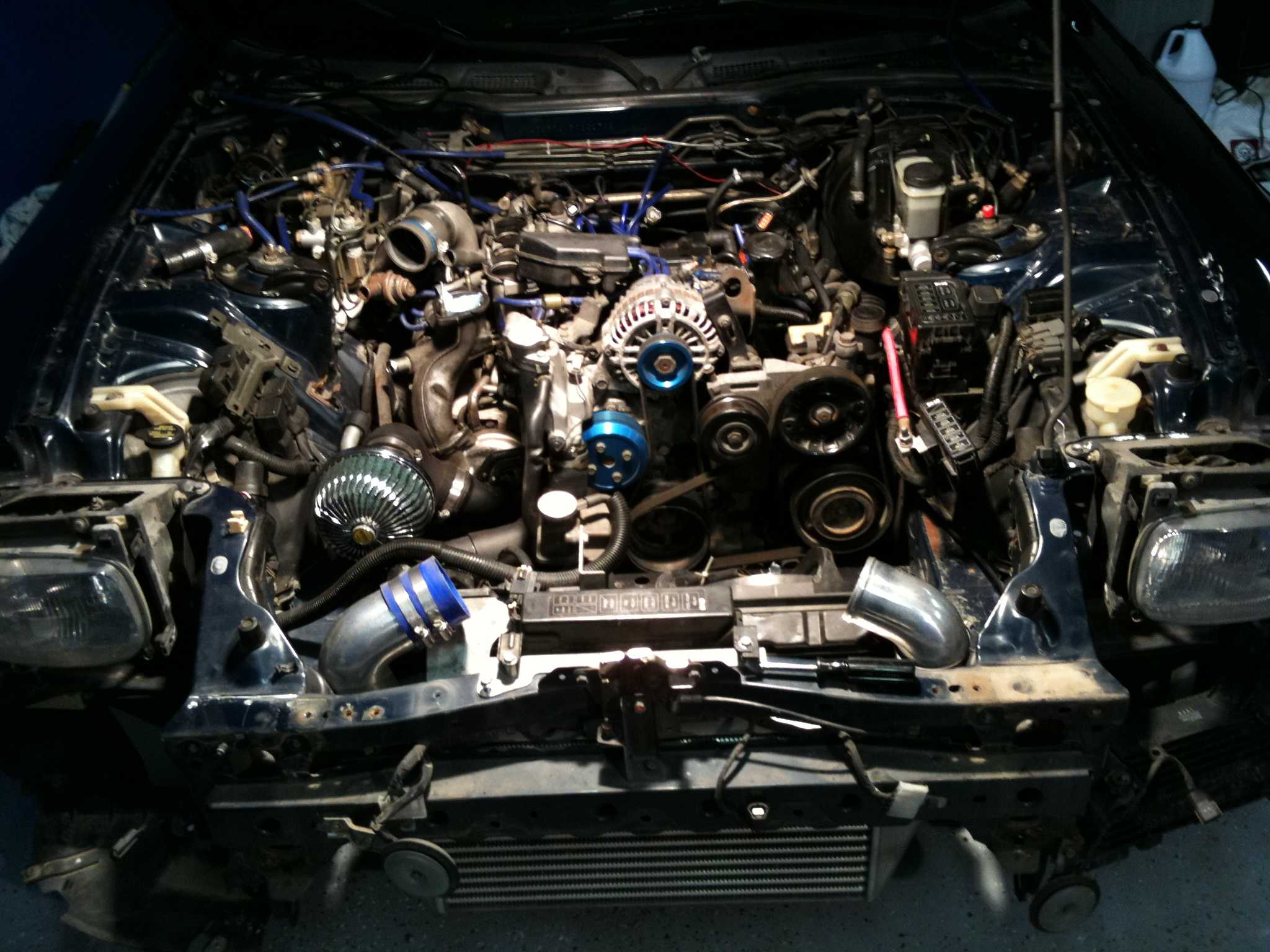
Start by recording the engine number, intake and exhaust configuration, ECU setup, turbocharger details and any symptoms reported before removal. Photograph hose routing, electrical connections and vacuum lines. Drain coolant and oil into suitable containers, then remove accessories and external components while keeping fasteners labelled by assembly.
A clean, covered bench is essential because rotary seals are easily damaged by grit. Use separate trays for front cover hardware, side housings, rotor components and eccentric-shaft parts. Bag each group with notes about its original position. If the vehicle is a daily driver, a service loaner programme can be useful while a long rebuild keeps the car off the road.
Do not assume every removed part should return to service. A low-kilometre engine can still have corrosion from moisture, worn bearings from poor lubrication or housing damage caused by detonation. Cleaning and inspection come before ordering the final parts list.
Strip Down And Inspect Every Surface
Remove the engine from the vehicle and mount it securely. Take off the intake, exhaust manifold, oil pan, front cover, water seals and ancillary brackets. Mark the direction of the rotors and note the position of each side seal, corner seal and spring. The eccentric shaft should be supported as the housings separate to prevent accidental damage.
Once split, wash the housings with a suitable solvent and dry them immediately. Inspect chrome plating for flaking, scoring and exposed aluminium. Check the trochoid surface under strong light, then inspect side plates for wear around the oil and water passages. Any deep groove that can catch a fingernail deserves professional assessment or replacement.
Measure the eccentric shaft journals for taper, out-of-round wear and scoring. Inspect main and rotor bearings, dowels, oil-control rings and seal grooves. Check the oil metering system, oil injectors and coolant passages. A blocked injector or deteriorated hose can undermine a fresh rebuild within minutes of startup.
Choose Reusable Parts With Measurements
Rotary engines depend on carefully controlled clearances. Apex seals need free movement in their grooves, side seals must sit correctly without binding and corner seals must match their intended positions. Never mix seal components casually between rotor types or rely on visual inspection alone.
The following comparison helps separate common inspection priorities for popular Mazda configurations:
| Area | 13B street or turbo build | 20B three-rotor build |
|---|---|---|
| Housing count | Two rotor housings plus side housings | Three rotor housings plus additional interfaces |
| Main concern | Housing wear, seal condition and shaft alignment | Alignment across more housings and greater assembly complexity |
| Parts planning | Strong aftermarket and used-part support | Scarcer components and higher sourcing risk in Australia |
| Measurement focus | Bearing clearance, side seal fit and rotor tip condition | All 13B checks plus shaft runout and stack alignment |
| Cooling demand | Critical for turbo applications | Especially demanding under sustained load |
Use Plastigage only as a secondary check where appropriate; micrometers and bore gauges provide more dependable results. Compare every measurement with the correct factory limit, not a generic rotary specification. The rotary reference library provides broader technical material for identifying engine variants and planning a rebuild.
Prepare New Parts And Set Clearances
Before assembly, deburr suitable components, clean all oilways and wash new bearings and seals in clean engine oil where specified. Verify that replacement apex seals have the correct thickness and groove profile. Turbocharged engines may use different seal choices from a naturally aspirated street engine, and an aggressive porting or boost combination can change the required preparation.
Dry-fit the eccentric shaft, bearings, rotors and housings to confirm that the stack turns smoothly. Measure end float, bearing clearance, rotor side clearance and seal protrusion. Check that dowels are seated fully and that water seals are correctly sized. Replace damaged O-rings rather than attempting to reuse flattened ones.
Porting also deserves restraint. A street-driven RX-7 in Melbourne or Perth may spend more time idling in traffic than operating at high rpm, so an enormous peripheral port can create poor manners and increased heat. Match port timing, turbo selection, exhaust sizing and engine management to the intended use.
Assemble The Rotary Core In Sequence
Lubricate the eccentric shaft and bearings with assembly oil, then install the first rotor with its seals, springs and oil-control components in their marked positions. Fit the correct side seals and corner seals, applying the specified sealant only where required. Excess sealant can migrate into oilways or coolant passages.
Lower the housing into place without forcing it over the seals. Continue the rotor, intermediate housing and side housing sequence while checking that each seal remains correctly located. Install through-bolts and nuts progressively in the factory pattern, bringing them to final torque in stages. Rotate the shaft by hand after each major step; tight spots indicate a problem that must be corrected before continuing.
Complete the front cover, rear cover, water seals, oil pan and accessories using new gaskets and seals. Prime the oil system before the first start. Disable fuel and ignition, then crank until oil pressure is confirmed. Check for leaks, verify coolant circulation and confirm that throttle, idle-air and ignition systems are operating correctly.
Run In, Tune And Record The Build
Initial running should be controlled and monitored rather than treated as a normal drive. Watch oil pressure, coolant temperature, intake temperature, fuel pressure and wideband readings. The wideband O2 guide is relevant when checking mixture accuracy on a turbocharged RX-7, especially after injector, exhaust or ECU changes.
Use conservative boost and ignition settings until the seals have bedded and the engine has proved stable. Avoid prolonged idling, repeated cold starts and extended high-rpm operation during the early running period. Follow the lubricant and break-in approach appropriate to the seal manufacturer and engine builder rather than applying a universal rule.
Final Workshop Checks
Before the first road test, verify:
- Oil pressure, coolant level and belt tension
- Fuel leaks, vacuum leaks and electrical grounds
- Ignition timing, idle control and boost reference lines
- Fastener marks, fluid levels and sensor readings
During the first drives, record:
- Cold-start behaviour and hot restart performance
- Oil consumption and coolant temperature
- Wideband mixture under load
- Any unusual noise, vibration or hesitation
Keep the measurements, seal brands, clearances, photographs and tuning revisions with the vehicle documentation. That record is valuable for future servicing, insurance discussions and any state inspection of a modified car. Use the factory data, measure every critical interface and document the rebuild as carefully as you assemble it.