
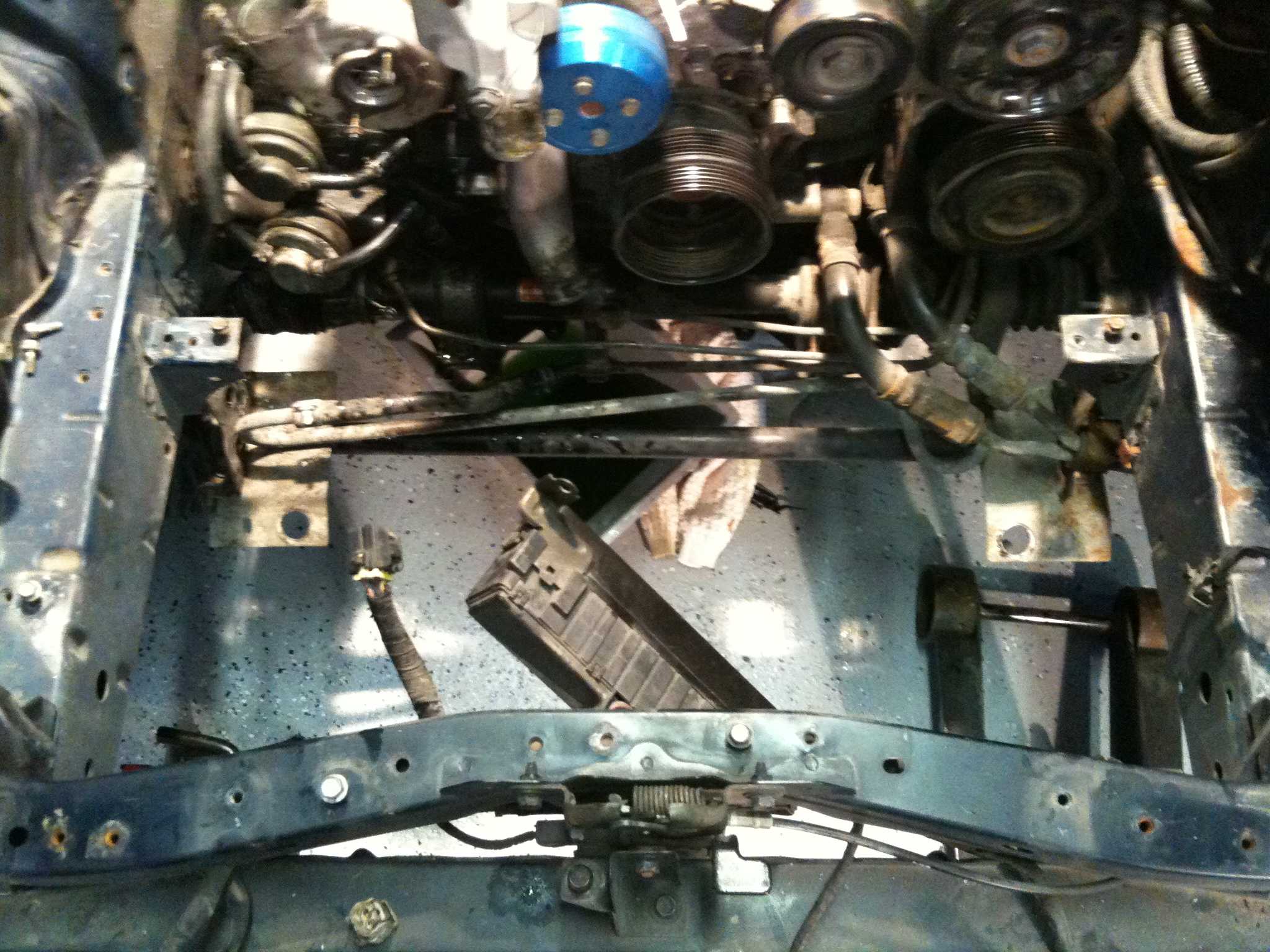
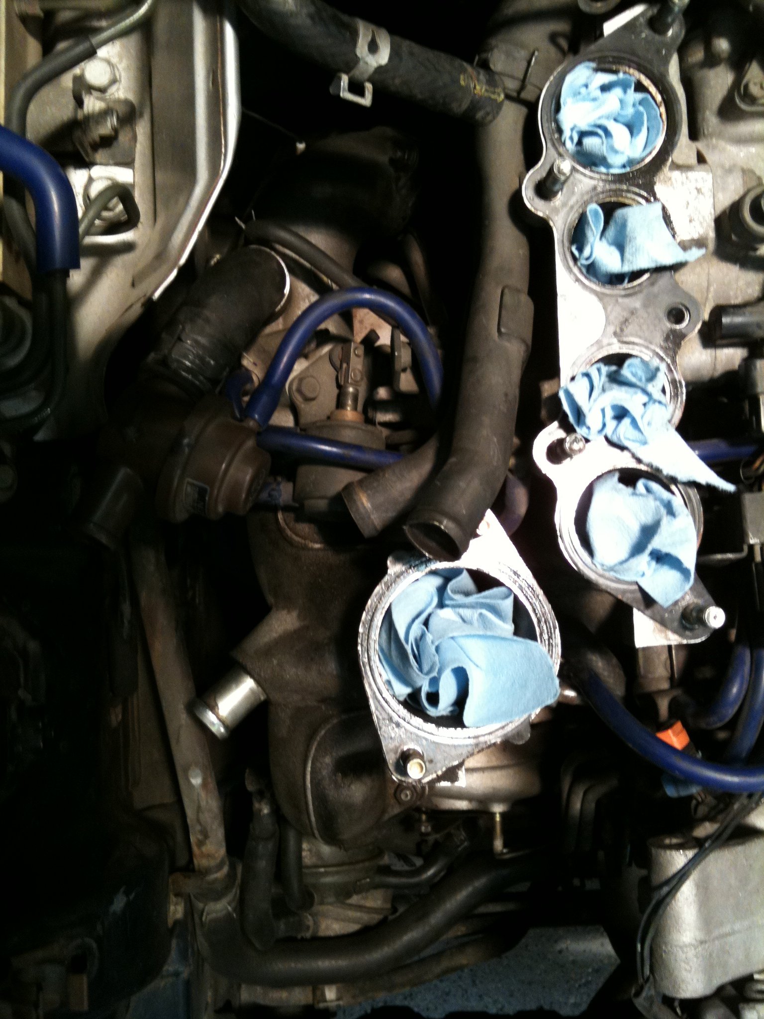
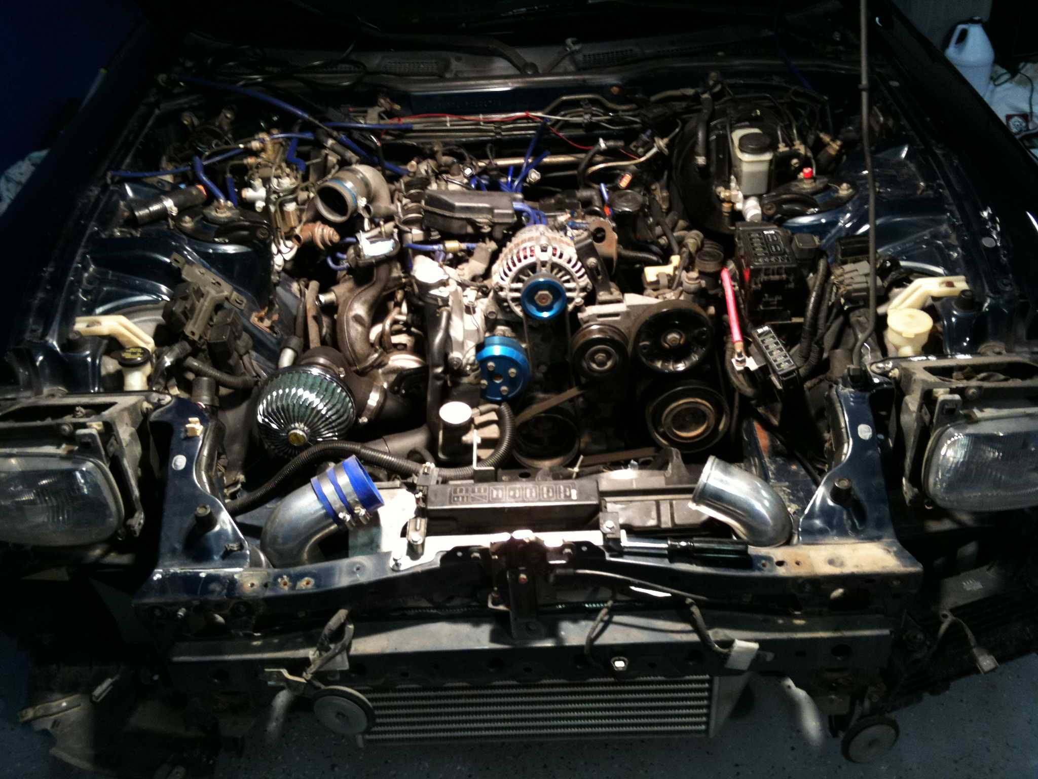
Configuring a PowerFC for a 20B-REW Triple Rotor
The 20B-REW’s three rotors provide a factory displacement of about 1,998 cc, but a PowerFC can only use the hardware and signals actually fitted. Establish whether the car retains its original electronics or uses a converted factory system. That choice determines which inputs require calibration and which functions remain available.
Apex’i PowerFC is more than a set of performance presets. Its ignition, injection, idle and protection maps translate engine needs into repeatable operating strategies. The 20B-REW still needs individual treatment: compressor housing geometry, port condition, injectors and fuel all alter what a numerical map should achieve.
Reliable tuning begins with measurements rather than a downloaded base file. Record wideband data, crank and cam signals, coil events, injector pulse width, temperatures and operating load. A workshop idle alone cannot validate the calibration, while unreliable sensors can make a healthy engine appear inconsistent.
Australian use adds useful constraints. The car is right-hand drive and runs on the left; road speed appears in km/h, temperatures in °C, and workshop gauges may show kPa, bar or psi. Fuel can be 91, 95 or 98 RON, with E10 availability differing between cities and regional routes. Imported parts also cross borders, currencies and corrosion-prone shipping routes.
Establish the exact hardware baseline
Document the engine and its supporting systems before touching a map. Record the 20B-REW build, forced-induction hardware if fitted, camshafts, intake tract, exhaust, injectors, coils, sensors and fuel pressure. Check that the wideband sensor is correctly heated and installed, while the coolant, oil and inlet-temperature sensors report plausible values.
TurboRX7’s PowerFC map parameters provide a useful map-order reference, although the hardware audit still comes first. Confirm the trigger pattern and tooth count, crank TDC reference and coil wiring so the ECU can place every ignition event correctly. An offset base-timing error then appears throughout the calibration and can hide a mechanical fault.
Decide whether the installation uses TPS, MAP or MAF for load, and assign every switch and sensor a stable reading. Check redundant inputs and set sensible rev, temperature and low-pressure cut-outs. The PowerFC should identify a failed input before that input creates an uncontrolled mixture.
Build the map from measured inputs
Start with injector sizing, fuel pressure and wideband calibration. A pulse width has little meaning if injector flow, impedance or fuel pressure differs from the assumptions behind it. Log lambda or calculated AFR from a stable warm idle, then correct the sensor rather than compensating through the ignition map.
Use staged targets and keep the first values conservative. The comparison separates a safe commissioning calibration from a verified operating map. Verification means supporting evidence from repeatable logs, not simply using a file downloaded from another RX-7.
| Area | Commissioning map | Verified operating map |
|---|---|---|
| Ignition | Conservative base timing confirmed with a timing light | Advanced timing supported by repeatable combustion checks |
| Injection | Wideband-corrected warm idle and conservative light-load targets | Load-based targets matched to measured injector flow and fuel pressure |
| Idle | Stable mechanical idle with generous airflow | Tuned idle that survives warm restarts and accessory loads |
| Protection | Conservative rev, temperature and fuel-pressure limits | Limits matched to validated hardware and the operating envelope |
Work through idle, light part-load, full part-load and high-load cells in that order. Allow the fuel and cooling systems to reach thermal stability before adding load. If a turbo is added later, wastegate, MAP and EGT functions must be established before raising boost rather than disguising a boost-control problem with ignition retard.
Set ignition and tune by load
Verify base timing mechanically, then let the map add corrections for load and heat. A practical starting range can be established from the engine builder and verified on the current fuel, but published 20B figures are not transferable specifications. Pull timing gently while watching lambda, charge temperature and any evidence of detonation.
Rich mixtures can hide knock, while lean mixtures can increase combustion temperature. Use wideband readings, cylinder-pressure data where available and EGT as supporting information rather than a substitute for knock detection. If engine output falls short of expectations, inspect spark plugs, lead seals, injectors, base timing and cooling before moving the ignition target.
A night road account from another vehicle illustrates how a real ride can expose conditions that a workshop session cannot. On an Australian route, record ambient temperature, traffic, fuel type and altitude, then note the exact point of any hesitation or pinging. Separate drivability changes from map corrections and retest on a familiar stretch near Melbourne, Sydney or Perth.
Match calibration to Australian use
Plan separate maps for regular 95 or 98 RON fuel and E10 where the engine and fuel system are suitable. Australian workshop shorthand matters: “95 octane” on a fuel pump means 95 RON, not the US Research Octane Number. Colder, denser or higher-octane fuel can change charge temperature and knock margin, so ignition and enrichment assumptions must match the actual purchase.
Use metric expectations consistently in the display and log. A 1,500 rpm event is meaningful in any market, but road speed, coolant temperature and pressure readings must not be confused with imperial units. Choose limiter, shift and warning thresholds that suit the car, and make sure a right-hand-drive conversion has not reversed pedal, steering or display-related inputs.
The parts market is equally regional. JDM and USDM spares arrive through different channels, while Melbourne, Sydney and Perth workshops pay in Australian dollars for components listed in yen, dollars or euros. Account for GST, freight, lead time and corrosion protection, and retain receipts and serial numbers. TurboRX7’s FC3S VIN differences guide helps identify regional donor hardware; confirm the PowerFC hardware revision separately because a VIN alone does not identify every aftermarket board.
Commission the car and preserve the result
Begin the first drive with a saved baseline, a full tank of the intended fuel and all cooling systems checked. Let the engine reach full operating temperature, verify idle and part-load behaviour, then add load in controlled steps. Keep the first high-load pull modest and stop if warnings, inconsistent lambda, excessive temperatures or unusual noise appear.
After the run, compare the log against the map changes and save a new dated version rather than overwriting the known-good file. Repeat with the same fuel and similar operating conditions where possible. Record injector duty cycle, timing corrections, lambda targets and every mechanical adjustment in the build file.
Now open the PowerFC software, establish the baseline maps and complete a shakedown log before pursuing more output. Use the linked reference material to verify map order, archive each proven configuration with the car, and make the next adjustment from evidence recorded on the road.