
Routing Charge Pipes to Reduce FD3S Hot Soak
The FD3S Mazda RX-7 has a compact engine bay, sequential twin turbochargers, and limited room around the factory intercooler system. That packaging makes charge-air temperature sensitive to pipe length, radiant heat, airflow restrictions, and the time spent idling after a hard run.
A well-designed pipe route does more than create a tidy engine bay. It helps the intercooler receive cooler air, reduces pressure drop between the turbochargers and throttle body, and limits the amount of aluminium and silicone exposed to exhaust-manifold heat. The result is more consistent boost behaviour when the car is driven repeatedly.
Australian conditions make this especially important. A summer crawl through Sydney traffic, a humid Queensland afternoon, or a long run near Perth can push an FD3S into heat-soak territory quickly. Thinking about airflow and heat management before selecting pipe diameter can save considerable tuning work later.
Start With The Factory Airflow Path
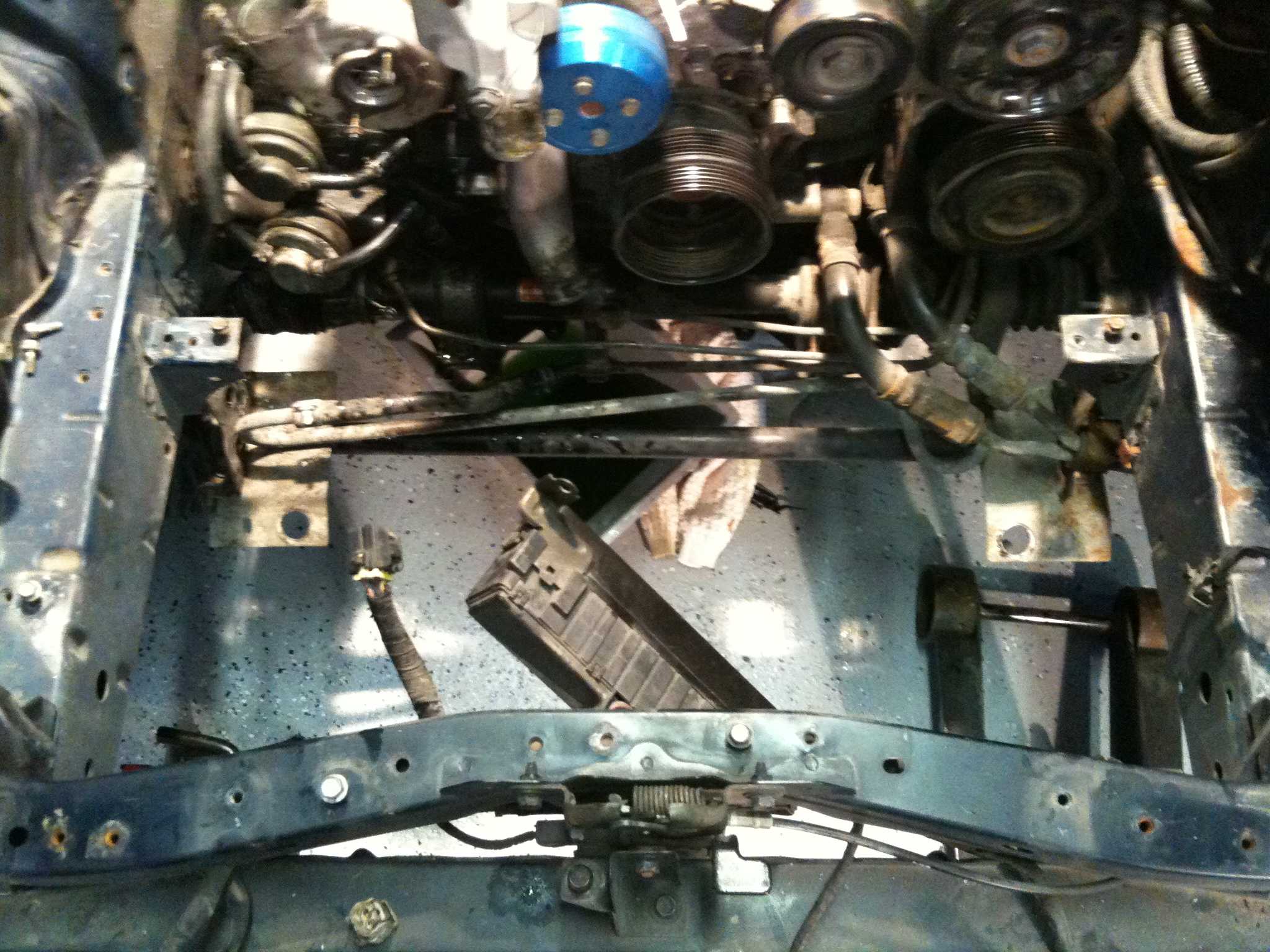
The standard FD3S layout places the intercooler near the front of the car, while the turbochargers sit deep in the engine bay. The charge-air path must therefore cross areas affected by the radiator, exhaust manifold, downpipe, fans, and under-bonnet pressure. Any replacement route should be judged against this complete thermal environment rather than pipe length alone.
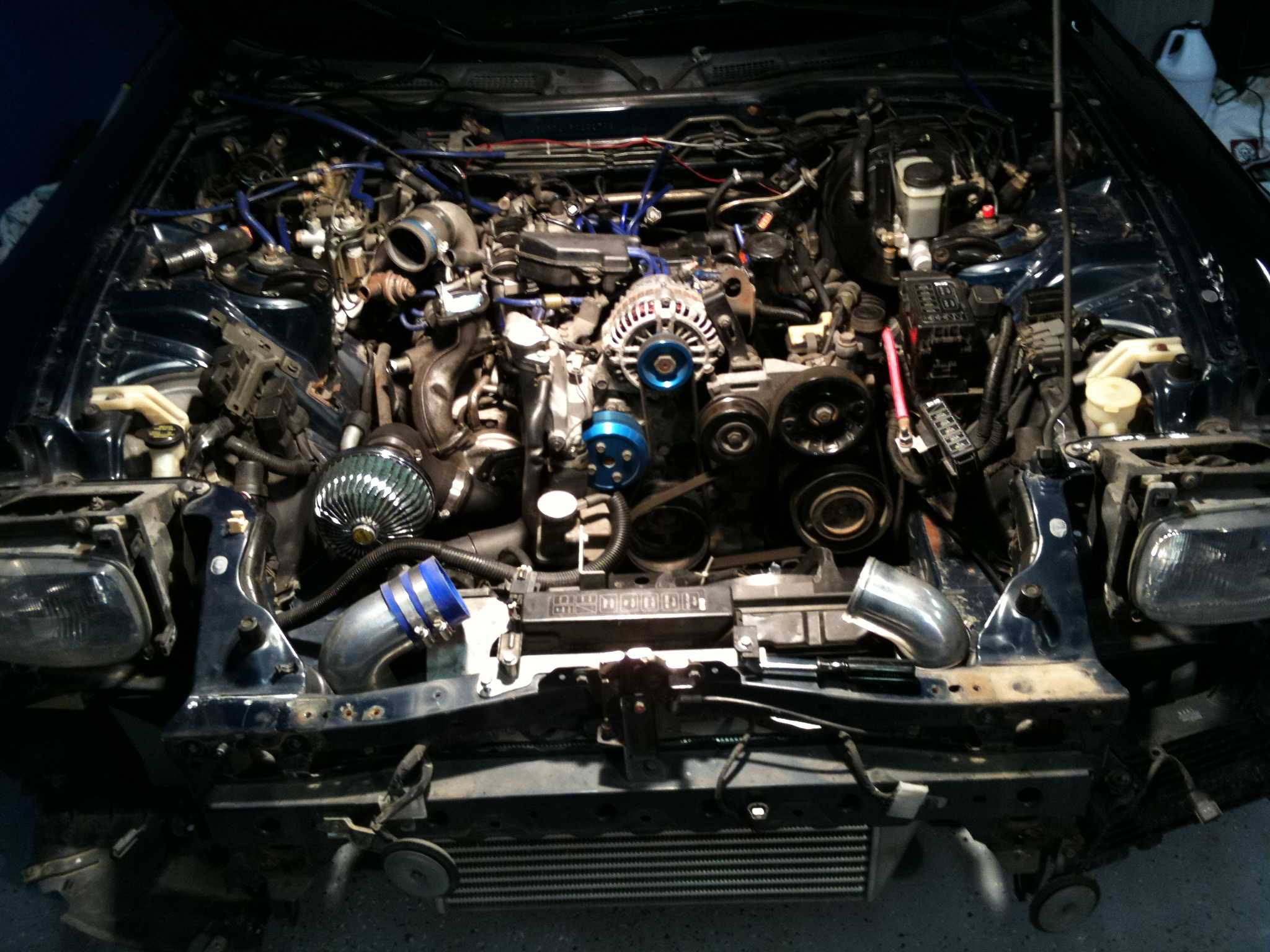
Keep the hot-side pipe as short and direct as practical, but avoid placing it directly above the exhaust components. A slightly longer route with an aluminium heat shield can perform better than a short pipe that absorbs radiant heat. The cold-side pipe should stay away from the radiator outlet and should receive airflow from the front ducting rather than from gaps inside the engine bay.
Factory dimensions, component locations, and original duct arrangements are worth checking before cutting or relocating anything. The OEM reference material on TurboRX7 can help establish what Mazda intended the surrounding airflow and cooling hardware to do.
Choose Diameter Without Chasing Maximum Size
Large pipes are not automatically better on a street-driven rotary. An oversized route adds volume that the turbochargers must pressurise and can create clearance problems around the bonnet, brake master cylinder, and radiator fans. For many FD3S builds, a carefully matched 2.5-inch system provides a useful balance between flow, response, and packaging, while higher-power combinations may justify a larger cold side.
The important measurement is the complete system: turbo outlet, intercooler core, bends, throttle-body entry, couplers, and joiners. Abrupt reducers and tight silicone elbows can create more restriction than a modestly smaller pipe with smooth bends. Bead-rolled ends, quality clamps, and supported joints also prevent boost leaks that can be mistaken for turbo or engine-management problems.
Avoid routing pipes so close to bodywork that engine movement causes contact. A small gap at rest may disappear under torque, especially if the engine mounts are soft or worn. Rubber-lined brackets should support long sections without hard-mounting the pipe to both the engine and chassis.
Separate Hot And Cold Zones
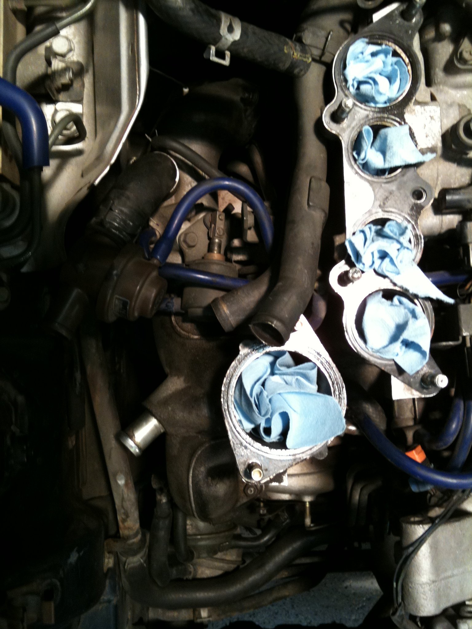
Thermal separation is central to reducing charge-air temperature after a heat-soaked idle. The hot-side pipe should have a clear barrier from the exhaust manifold and turbine housings. Use reflective shielding only where there is an air gap; wrapping a pipe tightly can trap heat and moisture, while wrapping exhaust parts can raise component temperatures if the installation is poorly ventilated.
The cold-side route needs protection from heat released by the radiator and engine. A simple aluminium barrier between the pipe and radiator outlet can help, especially when paired with a sealed intercooler shroud. The goal is to force ambient air through the intercooler core instead of allowing it to spill around the sides.
A polished pipe may look sharp at a show, but finish is secondary to location and airflow. Black ceramic-coated or insulated hot-side components can reduce radiant transfer, while a clean, dull-finished cold-side pipe may remain cooler when it sits behind effective ducting.
Build The Front Ducting Around The Intercooler
An intercooler cannot reject heat efficiently if air can bypass the core. Check the bumper opening, undertray, side gaps, and radiator seals. The duct should guide incoming air through the intercooler and then provide a controlled exit path into the lower-pressure area behind it. Adding a large core without correcting bypass paths can increase thermal mass while delivering little improvement in repeated runs.
The Australian aftermarket often includes large front-mount intercoolers designed for high-output builds, but a core that blocks the radiator may create a separate cooling problem. This matters in places such as Brisbane or Darwin, where high ambient temperature and humidity reduce the available margin. A balanced core, sealed duct, and healthy cooling system are usually more useful than the biggest available unit.
Check bonnet clearance with the engine rocking, not just with the car parked. A pipe that touches the bonnet insulation can transfer heat and produce irritating rattles. It can also damage a coupler over time if the engine moves during hard acceleration.
Account For Driving And Tuning Conditions
Hot-soak testing should include the conditions the FD3S will actually see. Measure intake-air temperature after a highway pull, after several minutes at a servo, and immediately after returning to boost. A route that performs well at speed can still absorb heat while idling because the intercooler receives little ram air and the engine bay fills with warm air.
For modified sequential-turbo systems, pipe routing must also preserve predictable valve operation and stable pressure signals. Keep blow-off or bypass-valve references short and secure, and inspect every coupler after heat cycles. If the car uses an Apexi PowerFC setup, intake-temperature trends and boost response can reveal whether a routing change has helped or simply shifted the restriction elsewhere.
Fuel quality and calibration matter as well. Australian pump fuel varies by location, and E85 availability is uneven outside major centres. A tune developed in cool workshop conditions should not be treated as proof that the car is safe after a hot afternoon in Adelaide traffic. Monitor knock response, air-fuel ratio, boost, and intake temperature under repeatable conditions.
Compare Routing Priorities Before Fabrication
The best layout depends on the intended use, turbo system, intercooler position, and power target. A street car that spends time in Melbourne commuting conditions may benefit from compact pipes and strong shielding, while a track-focused RX-7 can accept more fabrication to prioritise unrestricted airflow and rapid temperature recovery.
Peripheral porting and aggressive boost can change the thermal load substantially, so the pipe plan should match the engine’s actual operating range. This discussion of street peripheral-port limits is useful context when deciding whether a high-temperature, high-flow arrangement is appropriate for a road car.
| Routing approach | Main advantage | Main risk | Suitable use |
|---|---|---|---|
| Short hot side with shielded cold side | Quick response and low heat exposure | Tight clearance around turbo hardware | Street and responsive track builds |
| Large front-mount with long pipes | Strong high-power flow potential | Greater volume, lag, and radiator obstruction | High-output track cars |
| Compact side-mount replacement | Good packaging and simpler ducting | Limited cooling capacity at high boost | Mild street upgrades |
| Fully sealed front duct with moderate pipe size | Consistent temperatures in traffic | Requires careful bumper and undertray work | Australian road use |
Before final welding, mock up the route with temporary tubing and check fan clearance, bonnet movement, steering access, serviceability, and oil-filter removal. Record intake temperatures before and after each change, then keep the layout that performs in repeated use rather than the one that merely looks impressive.
Use the factory references, cooling observations, and PowerFC data together when refining an FD3S. Careful charge-pipe placement can make a rotary feel more consistent on a hot Australian day, so document the measurements and share the finished setup with the TurboRX7 enthusiast community.