
Sizing a dual-pass intercooler for high-horsepower rotary builds
A dual-pass intercooler can place a large heat-rejection surface into a tighter engine bay, which makes it attractive for Mazda RX-7 rotary builds where space, airflow and weight compete. Its second pass through the core does not automatically mean more capacity; useful sizing depends on core geometry, measured airflow and the restriction it creates.
Sizing a dual-pass intercooler for a high-horsepower build starts with the heat entering the charge pipe. A 13B or 20B installation can vary enormously with turbo choice, boost, cam timing, fuelling and how often it is driven hard. The same hardware can behave differently on a cool dyno day and in a hot, slow-moving traffic queue.
Australian conditions make those differences practical. Melbourne, Adelaide and Brisbane can experience summer ambient temperatures above 35°C, while regular 100–110 km/h motorway use and towing expose a car to sustained high-load conditions. A cooler adequate on a short dyno pull may lose its margin after heat soak.
Start with heat load rather than core dimensions
For a conventional air-to-air unit, “dual-pass” describes the route of intake air through the fin stack, not a coolant circuit. Two passes can improve heat density within a fixed package, although extra bends, tighter fins and the maker’s core design may also increase pressure drop. Treat the label as an architecture, not a performance figure.
Estimate duty from airflow and temperature reduction. Heat load in kilowatts is approximately airflow in kilograms per second × 1.005 × temperature drop in °C. At 1.5 kg/s and a 40°C reduction, the cooler rejects about 60 kW. Compare this at the hottest inlet over a sustained full-load run; published capacity often assumes favourable inlet temperature and unlimited airflow.
Set outlet-temperature and pressure-drop limits from compressor maps and intended use. Street cars may tolerate some margin above ambient; repeated full-power runs need more capacity. Colder charge supports knock margin but cannot replace boost and ignition control. Factory records in the TurboRX7 technical archive help establish the original cooling arrangement, while final sizing should rely on logged data and flow testing.
Build the sizing brief
Start with these heat and airflow inputs:
- Establish the compressor’s likely airflow range from corrected maps.
- Record boost, inlet temperature, outlet temperature and ambient temperature.
- Calculate expected heat rejection at the power and airflow actually planned.
- Separate a single maximum-power event from repeated hard driving.
Use these selection criteria:
- Set a total pressure-drop ceiling that protects spool and compressor output.
- Require measured airflow at the intended static pressure, not the peak fan rating.
- Confirm radiator capacity, fan drive and charge-pipe space before choosing dimensions.
- Allow access for sensors, drains, clamps and future servicing.
Do not select by advertised horsepower or heat-rejection headline alone. Compare test conditions and allow margin for hot soak and conservative catalogue figures. The intercooler’s rejected heat also raises radiator load, so cooling-system capacity belongs in the same calculation. Keep the path from compressor outlet to throttle body within the pressure budget; a superb core can still be undermined by crushed or sharply curved charge pipes.
Compare the core architectures
The useful comparison is between heat capacity, restriction and packaging:
| Architecture | Heat-rejection potential | Pressure-drop behaviour | Best fit |
|---|---|---|---|
| Wide single-pass core | Very high for the available frontal area | Usually the lowest restriction at a given area | Maximum power when the engine bay can accept it |
| Compact single-pass core | Moderate | Can restrict badly as airflow rises | Street or touring use with modest boost |
| Short dual-pass core | High for its package | Often higher than single-pass because of turns and fin density | Constrained bays needing strong charge cooling |
| Flow-optimised dual-pass core | High | Depends heavily on tube path, fin pitch and core support | High-output builds matched to measured compressor maps |
A wide single-pass core is straightforward when frontal area is available. A dual-pass layout can suit a tight bay, but seller terminology is inconsistent and the claimed benefit may reflect a particular core. Request airflow and pressure-drop curves in the same units before comparing them.
Chassis reaction matters too: several hundred kilowatts can upset the FC3S platform through tyre load, pitch and rebound damping. The site's FC3S suspension refresh guide explains the bushes, ball joints and tie rods that should be checked before more boost is added.
Match plumbing, sensors and controls
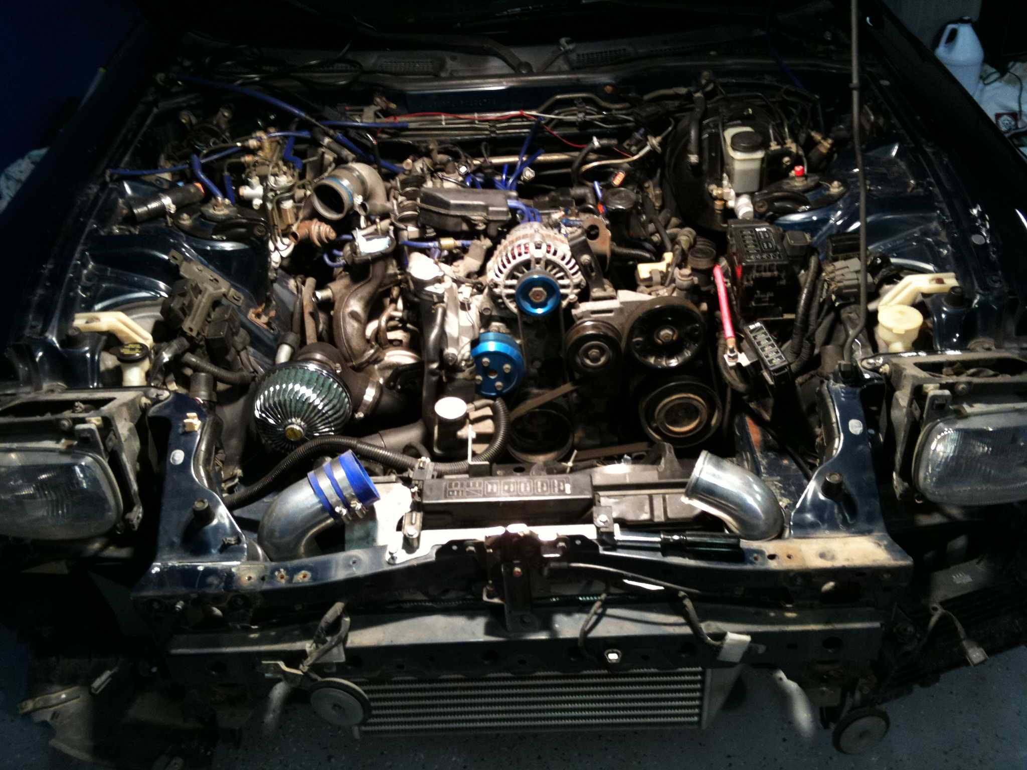
Plumbing can erase the advantage of a thermally capable core. Use mandrel-bent pipes with smooth bends, supported couplers, correct clamps and a clean path from compressor to throttle body. Keep the inlet away from exhaust heat, avoid sections that collapse under boost, and use matched pressure taps to separate core restriction from pipe losses.
Fit sensors where they can be trusted. Log manifold pressure, intercooler inlet and outlet temperature, ignition advance, lambda and fan duty during a full pull. For lambda control, the wideband oxygen sensor guide covers probe placement and configuration; a wideband sensor measures exhaust oxygen, so it complements rather than replaces charge-temperature logging.
Engine management must work with the cooler. Establish baseline fuelling and ignition, add boost in small increments, and watch for lean corrections, knock retard and rising outlet temperature. PowerFC or another ECU can log the relationships, but repeated heat-soaked pulls are needed for real-world tuning.
Validate the build in Australian conditions
Validate in the climate and duty cycle where the car will live. Repeat logging after a warm drive, then compare hot and cool inlet temperatures. Include low-speed, high-ambient operation as well as maximum-power running; an intercooler can perform well at high flow yet leave charge temperature high during a slow, hot road test.
Packaging must suit Australian left-hand-drive cars and touring habits. Local specialist suppliers and fabricators cluster around cities such as Melbourne and Sydney, while many parts still arrive through overseas distributors. Shipping a core does not replace local pressure testing and bracket verification. Towing a caravan or boat on 100–110 km/h motorway sections demands stable piping and cooling under sustained load.
Legal checks belong in the plan. An engine or intercooler change is not automatically approved or prohibited, but the car must meet applicable state registration and roadworthiness rules. For an imported FC3S, check the VIN, Australian Design Rule records and state inspection requirements, and keep invoices. Although it concerns Indonesian motorcycles, the Vulcan S insurance comparison illustrates a useful principle: compare comprehensive cover against third-party limits rather than judging cover by the headline premium.
Put the numbers into a sizing sheet before ordering: peak and sustained heat load, measured core pressure drop, required airflow, inlet and outlet targets, radiator capacity and available space. Order the core against those figures, preserve the test results with the build records, and validate the finished installation on a full heat-soaked pull before increasing power.