
Sizing an Intercooler Core for a Street-Driven FD3S
A street-driven FD3S rarely needs the largest core that physically fits. Its job is to control charge-air temperature reliably during warm-up, long climbs and the occasional burst of full throttle while preserving low-speed response, quiet operation and serviceable packaging. Oversizing can increase pressure drop, delay throttle response and create heat soak around the intake tract. Learn more about Rotary Basics.
Ambient conditions make that balance especially Australian. Melbourne can deliver a chilly morning followed by a hot afternoon, Sydney and Brisbane bring humid charge air and condensation risk, while Perth’s dry heat and dust reward plenty of radiator airflow. A setup tuned on a mild day may therefore feel very different in January traffic or during a run through regional Victoria. Learn more about Powerfc Tuning.
The right answer is a measured thermal target, not a universal width in millimetres. Core capacity, usable airflow, charge-path pressure loss and the cooling system must be considered together, then verified with intake-air-temperature logs after calibration.
Set the Heat and Airflow Targets
Begin with the heat the charge cooler must remove. For dry air, the rough relationship is Q = ṁ × cp × ΔT, where Q is heat rejected in kilowatts, ṁ is air mass flow in kilograms per second, cp is about 1.005 kJ/kg·K and ΔT is the temperature reduction across the core. At 1.5 kg/s and a 60°C drop, the cooler handles about 90 kW.
That calculation is a starting point, not a dyno result. Use boost, estimated compressor flow and measured inlet and outlet temperatures to build the case for a particular heat load. For a street 13B or a high-output 20B conversion, the useful question is how much heat the core can reject at the pressure drop the plumbing will tolerate.
Set an outlet-temperature target from local ambient rather than trying to force charge air to ambient temperature. For many street applications, an outlet around 30–45°C above ambient preserves useful density and a sensible knock margin. Lower targets increase condensation risk in coastal humidity, while higher targets make repeated hard runs less consistent.
Compare the Core Formats
Core size only matters if air passes through it effectively. Compare the formats by sustained heat rejection, frontal area, pressure drop and heat-soak behaviour, not by advertised power or fin count alone.
| Format | Sizing tendency | Street strengths | Main compromise |
|---|---|---|---|
| Air-to-air bar-and-plate | Moderate width with a deeper core | Strong response and simple plumbing | Pressure drop and duct transitions need care |
| Air-to-air finned | Wide frontal area, usually shallow to medium depth | High heat rejection at low fan speed | Packaging, fan power and heat soak |
| Water-to-air | Compact charge-air heat exchanger | Predictable temperatures with a controlled coolant loop | Pump, plumbing, radiator capacity and maintenance |
| OEM-style top-mount | Compact core with a short charge path | Factory-like layout and low installation effort | Limited frontal area and rapid parked heat soak |
A large finned core usually wins at low fan speed if the ducts, fan and radiator are arranged correctly. A compact water-to-air system can also suit a crowded FD3S, but it adds a pump, reservoir, plumbing and radiator heat that the pack must handle. Bar-and-plate cores often respond strongly, while an OEM-style top-mount position is tidy but vulnerable to parked heat soak.
Fit the Core Around the FD3S
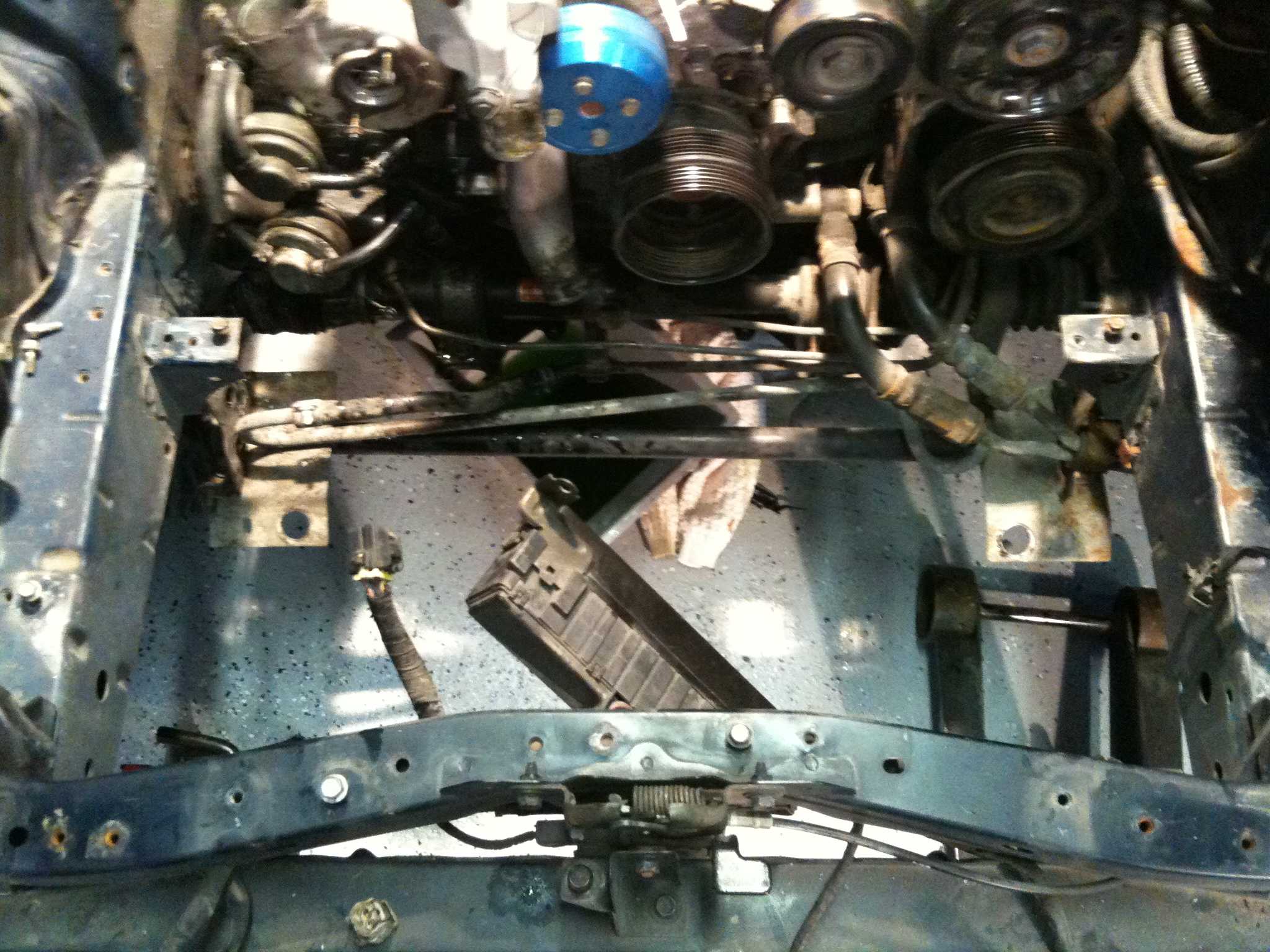
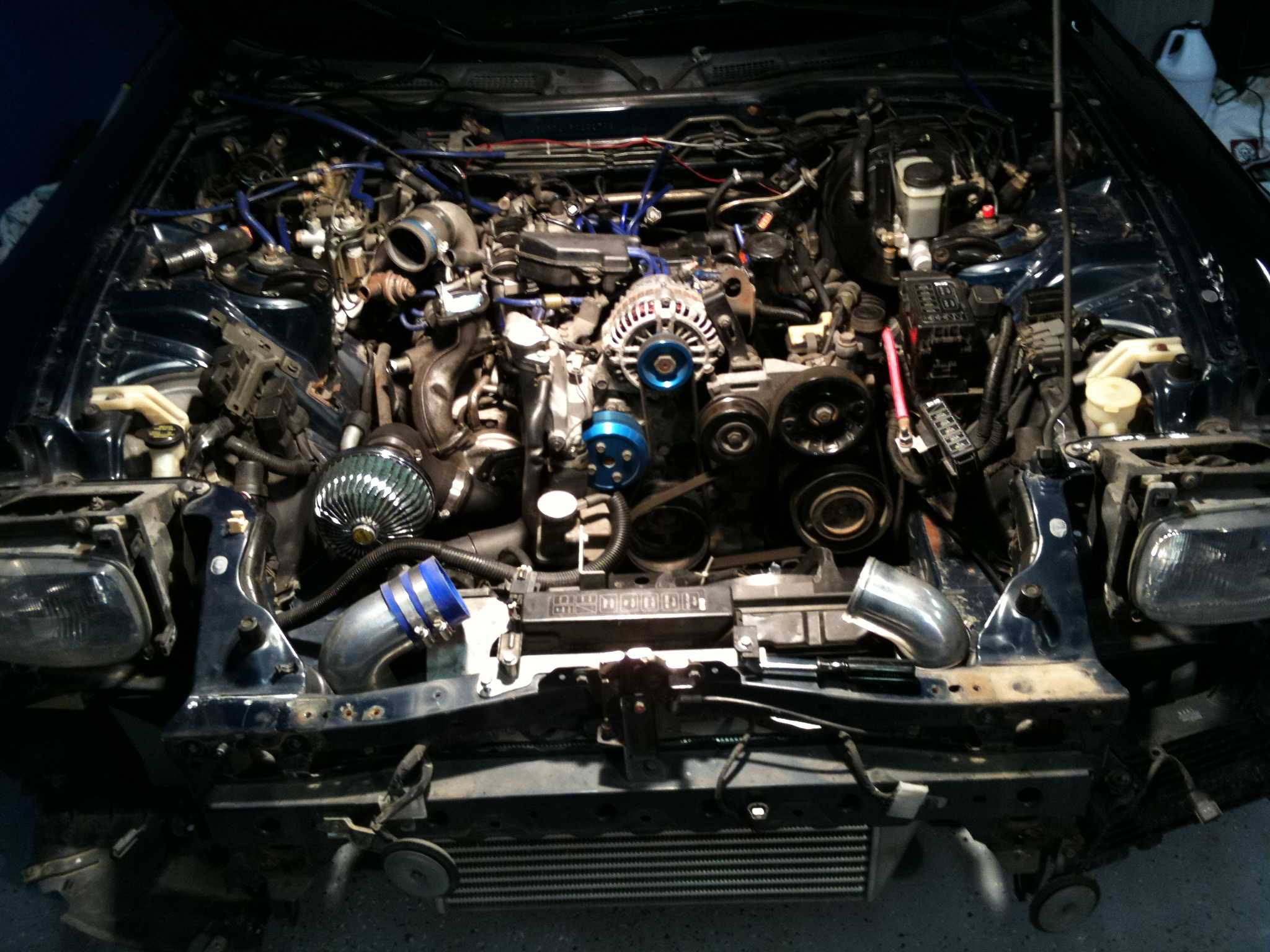
Start with the chassis, not the catalogue. Depending on its market and turbo arrangement, an FD3S may use a top-mounted cooler or a front-mounted installation. Available space around the radiator also varies with the front bumper, engine bay and whether the car is a sequential-turbo model. Measure the clear opening after accounting for guards, fans and the air box.
Use the [rotary basics] reference to keep compressor, exhaust and charge-air flow requirements in view. A larger intercooler cannot create compressor flow, and reducing boost to make the system feel manageable simply masks a sizing error. Keep inlet and outlet transitions smooth, avoid sharp internal bends and make removal practical for servicing the radiator and turbo plumbing.
Australian ute and towing use adds another constraint because sustained load and added vehicle mass reduce the margin for heat soak. The local used-import tuning scene makes spares and adapters easier to source, but listings often advertise peak boost rather than tested airflow and pressure drop. Prefer measured core data, then make sure the installation remains practical for the way the car is actually used.
Tune the System Around the Core
Installing a larger or more efficient core changes the temperatures and densities the engine-management system sees. A MAF- or MAP-based tune, boost control and ignition table may all need adjustment. The [PowerFC tuning guide] provides relevant background for checking temperature compensation, ignition timing and fuelling after the hardware changes.
Do not use extra boost to compensate for poor charge cooling. Establish stable manifold pressure and intake-air temperature first, then set fuel and timing around the engine’s knock and temperature limits. A controllable wastegate, properly sized bypass valve and leak-free boost plumbing help avoid compressor surge when a large core changes low-speed flow.
For water-to-air, include the electric fan, pump, thermostat, reservoir and radiator in the test. Confirm that the system cools during a long climb and recovers after a hot stop. For air-to-air, check pressure drop through the complete cooler and duct path rather than relying on the core’s clean-air figure.
Build a Street-Centric Sizing Checklist
A practical street-sized core should satisfy both the thermal brief and the daily-driver brief.
Thermal and performance checks
- Record peak and post-run intake-air temperature on representative drives and a long climb.
- Confirm quoted heat rejection at the airflow and pressure drop available in the installation.
- Choose an outlet temperature that preserves density without causing excessive condensation.
- Set boost, timing and fuelling after logging the cooler’s temperature behaviour.
Fitment and ownership checks
- Measure radiator clearance, duct losses, fan operation and access to service points.
- Confirm the radiator and fans can support the intended power at hot idle and while towing.
- Inspect hoses, clamps and coolant joints regularly, especially on water-to-air systems.
- Retain the core and calibration records for registration, roadworthiness and future changes.
A core that looks excellent on paper can still disappoint if hot air is trapped in the intake tract or the radiator cannot draw enough air. Use an efficient fan, seal the charge path where practical and provide a clean drain for condensate. Opening the bonnet during a hot stop can reduce heat soak while parked, but it does not replace adequate cooling.
Measure the available width, height and depth, log intake-air temperature across a warm drive and a long climb, and compare those results with verified heat-rejection data before ordering. Record the final duct sizes, core pressure drop and calibration settings using the TurboRX7 documentation, giving the next owner a clear baseline for the street-driven FD3S.