
Using PowerFC Datalogger to verify MAP sensor accuracy
MAP readings can appear believable while biasing boost control, ignition timing or fuel corrections on a 13B or 20B. A PowerFC log turns that suspicion into evidence by showing how manifold pressure changes alongside engine load. The rotary fundamentals provide a useful starting point for understanding the sensors and systems involved.
MAP is absolute manifold pressure, not boost above the atmosphere. A reading of 140 kPa with 100 kPa ambient pressure represents 40 kPa of boost, regardless of how the gauge is scaled. Checking the signal in absolute units prevents a healthy MAP reading from being mistaken for a boost-reading fault.
Australian conditions make a local baseline sensible. Brisbane, Melbourne and Perth normally sit near 100–101 kPa, but altitude, weather and pressure changes alter the reference. E10 is widely available, so fuel type and any closed-loop fuel correction should also appear in the log notes rather than being blamed on the pressure sensor.
A useful verification combines electrical checks, controlled engine states and repeatable logs. Begin with the connector and wiring, establish what the ECU sees before the engine starts, then compare idle, vacuum and positive boost. Only after those checks should sensor scaling or PowerFC calibration be adjusted.
Establishing a trustworthy baseline
First identify the exact MAP sensor, connector and calibration expected by the ECU. The OEM information library can help with factory wiring and specifications, while a service manual should confirm whether the sensor is referenced or supplied. Check supply voltage, ground integrity and connector pins against that documentation; do not assume every aftermarket MAP sensor uses the same 0.5–4.5 V curve.
Before starting the engine, close the throttle and compare the logged MAP value with a local barometer. The values should agree closely once the ECU has updated. Australian buyers should also verify part numbers: imported sensors can add customs, freight and GST, while a locally sold generic unit may have a different transfer curve. A cheap price is no substitute for matching calibration data.
Logging the signals that matter
In the PowerFC Datalogger, configure MAP as a primary channel and log it with TPS, crank speed, boost command, injector pulse or duty, and lambda where available. The PowerFC resource hub can support the wider setup and documentation. Keep the sample interval stable, and give every run a clear ambient-pressure and fuel-condition note.
Record three distinct states. Key-on engine-off establishes sensor offset; idle and a high-vacuum transition reveal the lower pressure range; a controlled positive-boost pass checks the upper range and response time. If a transient appears slow, confirm that the logging interval is not masking the sensor’s real behaviour. In Australia, label E10 separately from other fuels because adaptive fuel correction can change lambda and load response without correcting a faulty MAP signal.
Comparing pressure with expected behaviour
Expected pressure must follow physics, but it should not be reduced to one universal idle number. Porting, throttle body, cam timing, turbo control and boost leakage all affect the result. During boost, subtract local atmospheric pressure from logged absolute MAP: 140 kPa absolute at 100 kPa ambient is 40 kPa gauge.
| Logged pattern | Likely interpretation | Best next check |
|---|---|---|
| Key-on MAP differs from ambient | Offset or reference issue | Compare with a calibrated barometer |
| MAP remains near ambient at idle | Open circuit or scale error | Check voltage, wiring and TPS transition |
| Boost tracks command but remains low | Under-reporting or calibration error | Verify transfer curve, reference and boost leaks |
| MAP spikes or flickers | Loose connection, poor ground or heat | Inspect the loom and repeat hot and cold |
Read the log for offset, scaling, lag and noise rather than simply deciding whether MAP looks plausible. A constant error suggests calibration or reference-voltage trouble; pressure that fails to move with TPS or boost command suggests wiring or a failed element; abrupt spikes suggest connector or grounding faults. Compare suspect readings with a calibrated reference transducer or a known-good, specification-matched sensor before changing settings.
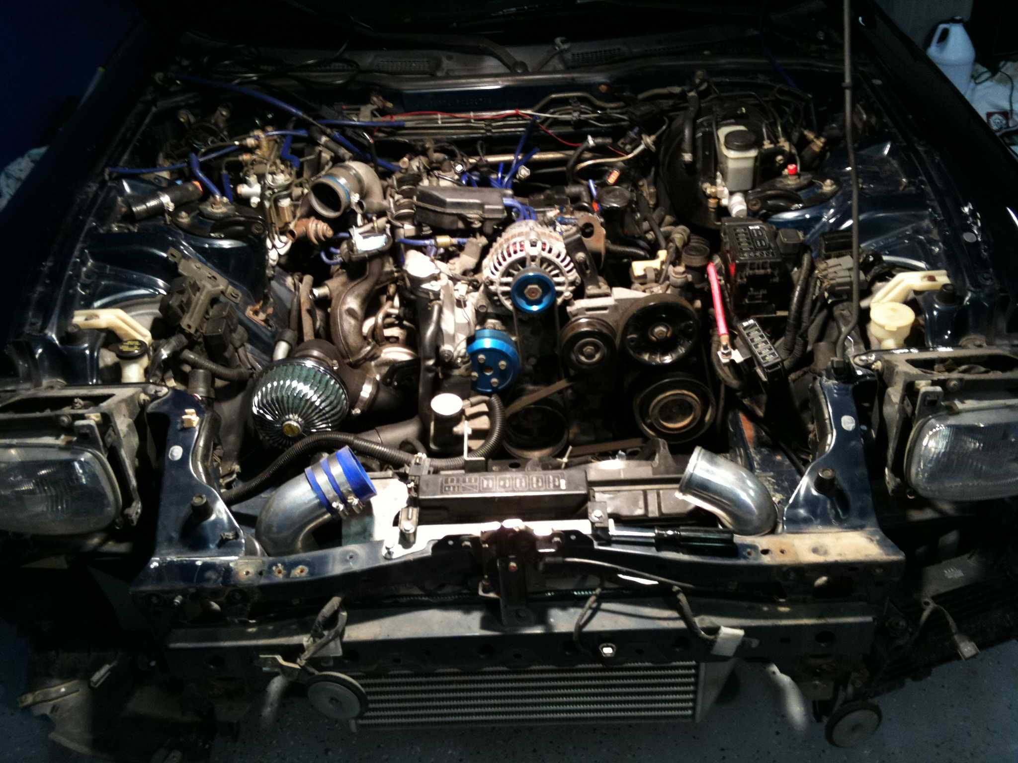
For a modified build, show-car styling ideas can prompt a review of non-stock engine-bay changes, but they are not calibration evidence. Electrical testing and the sensor’s transfer curve remain decisive.
Testing safely in Australian conditions
Keep the first pressure pass stationary or on a private closed course, and preferably a dyno if the car and data equipment are suitable. Australian left-hand traffic and state roadworthiness rules make an improvised public-road boost test inappropriate. Secure the laptop, cables and power supply so nothing enters the throttle or brake area.
Local climate can expose weak behaviour: Brisbane humidity can reveal condensation-prone connections, Melbourne temperature swings can make warm-up drift visible, and Perth dust can work into an unsealed plug. Inspect and protect those connections, then repeat the same run when cold and hot. In a right-hand-drive RX-7, an ergonomic footpeg reference is relevant to pedal clearance, although it has no effect on MAP accuracy.
Correcting errors and confirming results
Use the result to choose the narrowest corrective action:
- Confirm key-on MAP against local atmospheric pressure.
- Verify supply, ground, pins and sensor part number.
- Compare MAP with TPS, RPM, boost command and lambda.
- Repeat the run cold and hot to expose drift or noise.
- Swap in a calibrated reference or known-good matched sensor.
- Save the baseline, adjustment and repeat-test logs together.
Apply an offset correction only when the sensor response is otherwise linear and repeatable. Replace a sensor that is open, nonlinear or unstable, and repair wiring or grounding before recalibrating. After any change, repeat the identical test states and compare the three logs; a credible correction should move the complete operating window, not merely the idle value.
Run a key-on, idle and boost sequence now, save each log with city, ambient pressure, weather and fuel type in the file name, and take the evidence to an Australian rotary specialist or PowerFC tuner before making a calibration change.