
How to Fabricate a Battery Relocation Kit for the FD3S
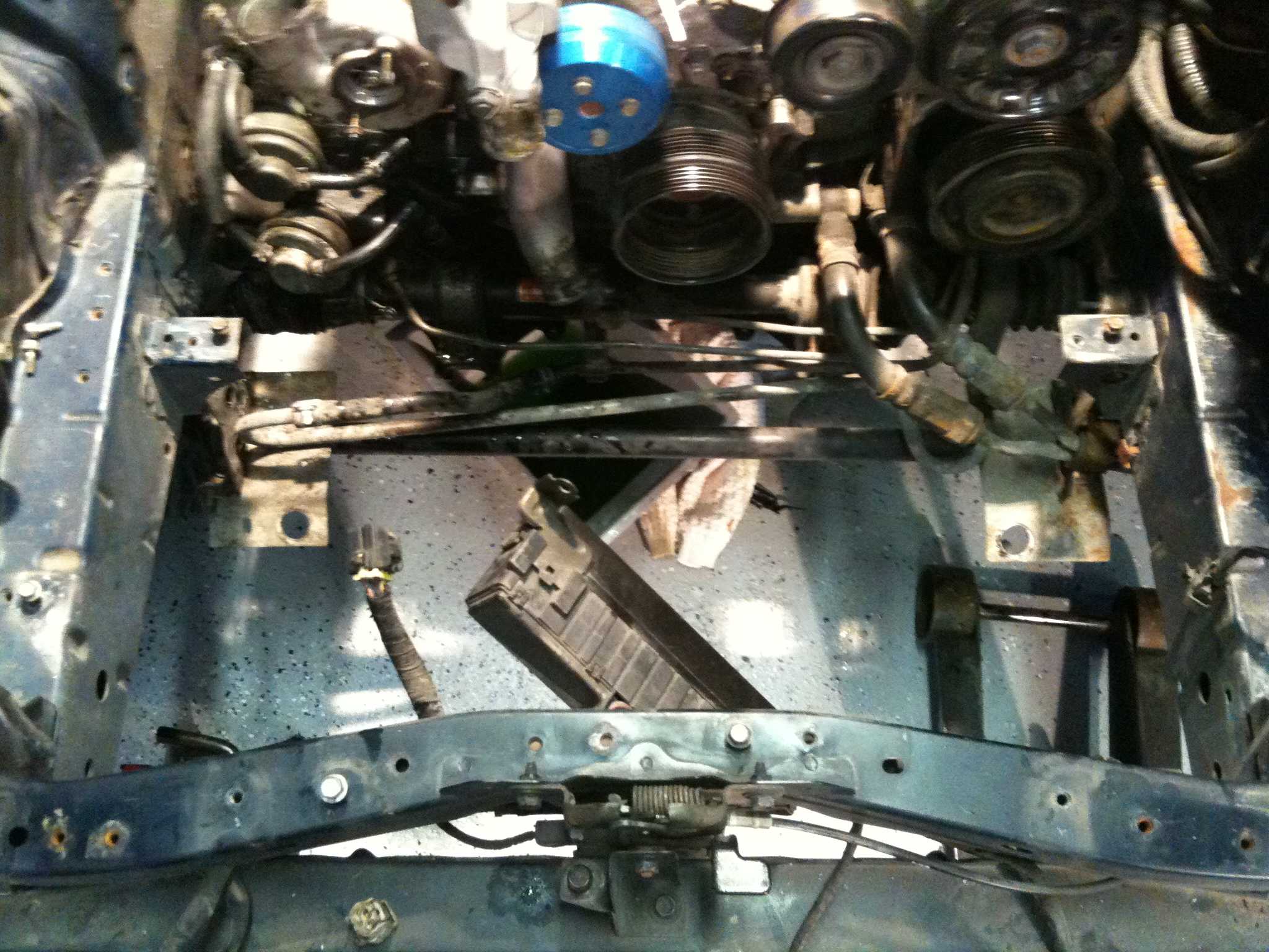
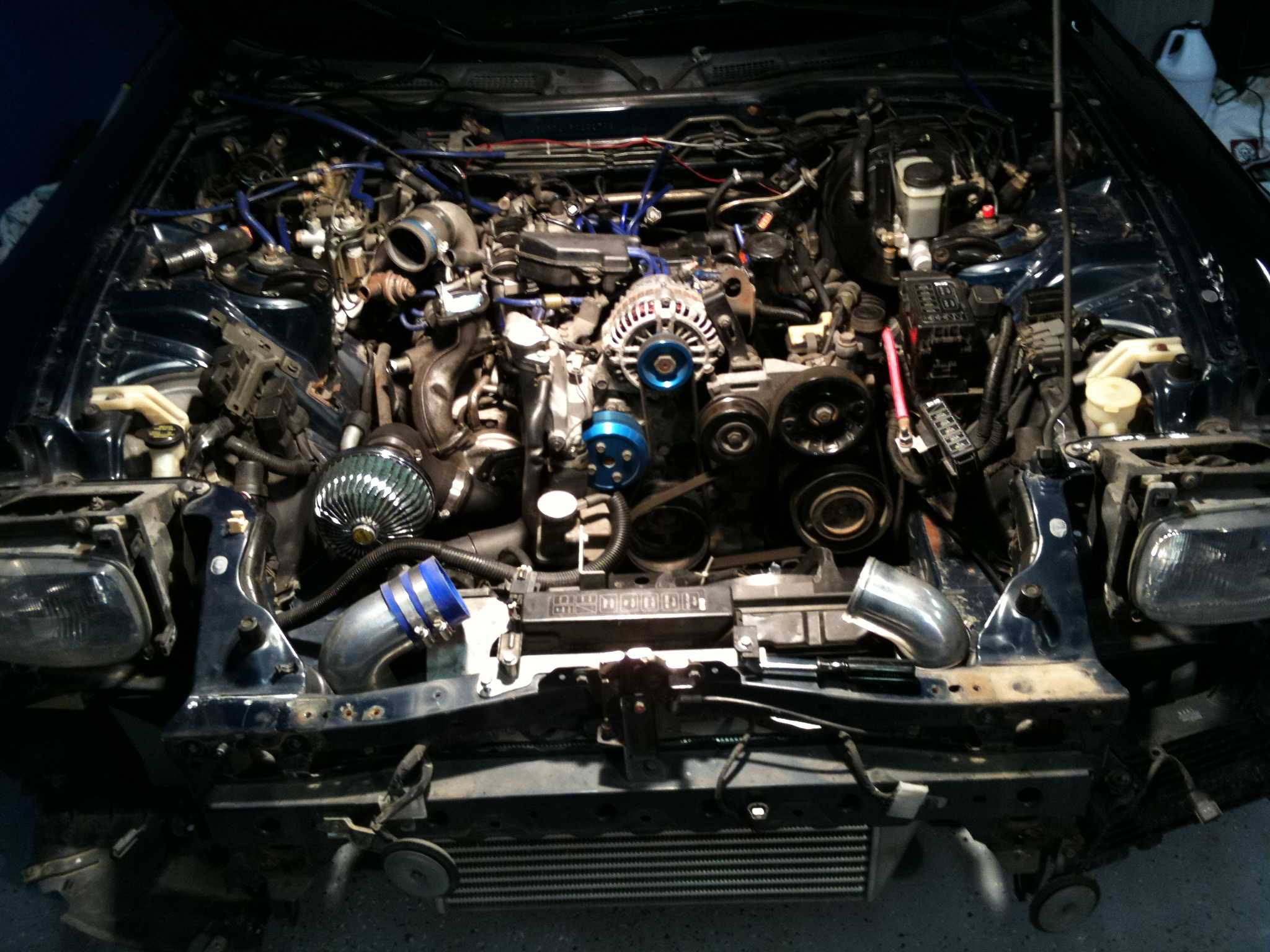
A battery relocation kit for the FD3S can free useful engine-bay space for cooling, wiring or exhaust work, but the finished installation must handle starter current, charging voltage and crash loads as competently as the factory system. The aim is a rigidly mounted battery, low-resistance leads and an electrical layout that leaves every ECU, relay and safety circuit working as intended.
This guide covers a rear-luggage installation using the existing battery type for most cars. Before cutting or drilling, identify the exact chassis revision and check its diagram; FD3S bodywork, battery trays and electrical details changed across the model run, so one generic kit rarely suits every car.
Confirm the chassis and choose a destination
Begin with the factory reference material for the car, then compare the original tray, battery dimensions, terminal positions and cable paths with the proposed rear location. Measure the full battery, hold-down and lid clearance rather than relying on catalogue dimensions. Record the positive and negative access directions before ordering any cable.
Australian examples may be left- or right-hand-drive grey imports, so inspect pedal-box and seat clearance before using the rear-seat area. Registration and roadworthiness rules are state-based across NSW, Victoria and Queensland; have the proposed restraint, terminal protection and cable route checked against local inspection criteria.
Plan the cable route and electrical connections
Map the positive feed from the battery to the starter and the negative return to the engine or factory earth point. Keep the run short, and do not make the body panel a high-current earth path. Existing engine-to-body earth straps should remain clean and intact.
The FD3S relay and load-shedding arrangement makes electrical load management particularly important. Retain the ECU power, alternator sense and battery-condition inputs, or reproduce them with thin, correctly terminated wires. A long lead that merely reaches the starter can make charging voltage or state of charge look wrong at the ECU.
Use cable sized from the measured starter load and run length, with the factory diagram taking priority; 25–35 mm² welding cable is a practical starting point for a long run, not a universal answer. Choose matching lugs for the battery posts, fit a properly rated main fuse where the design requires one, and seal every penetration with a suitable grommet.
Fabricate a secure battery tray
Form the holder from 2–3 mm steel, add flanged edges, and bolt it to reinforced body mounts with vibration-resistant hardware. A rubber mat and rigid clamp will stop the battery moving under braking; screws through thin boot carpet, the parcel shelf or rear-seat springs are not adequate restraints.
Coat the steel before fitting and keep bare battery terminals away from painted metal. Sydney’s salt-laden humidity, Melbourne’s damp winters and hot inland summers all justify careful sealing and corrosion checks. Common cable, terminals and AGM batteries are available through Australian outlets such as Repco or Supercheap Auto, but the tray itself should be locally made or modified to suit the car.
Terminate the leads and protect the wiring
Strip only enough cable for a clean termination, crimp tinned copper lugs with the correct die, then add adhesive-lined heat-shrink. Use a correctly sized pin-to-ring adapter only when the battery uses small posts. Route the loom through an existing bulkhead opening where possible; if new holes are unavoidable, inspect both sides for brake, fuel and factory wiring first.
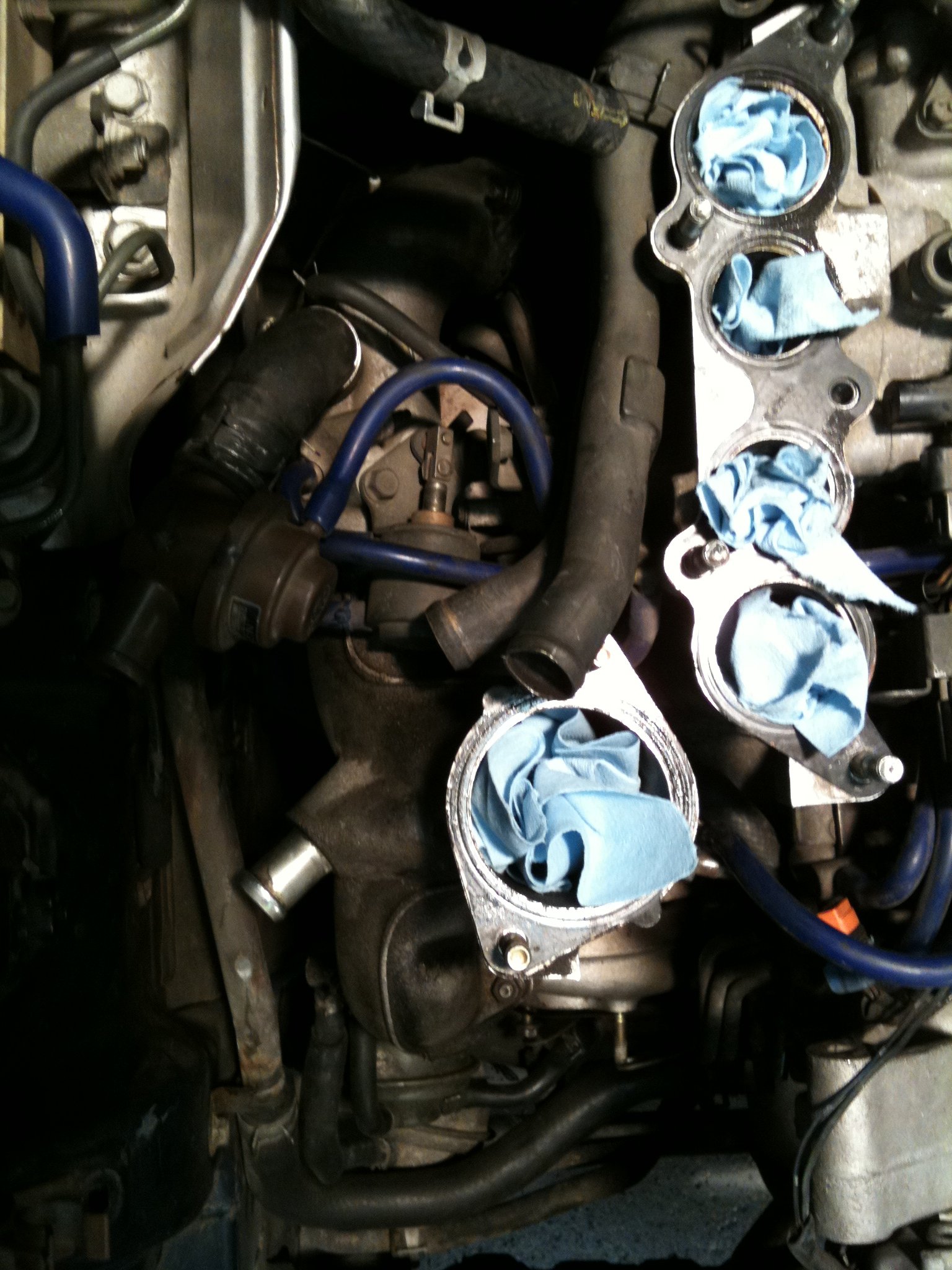
Keep cables clear of the exhaust manifold, turbo plumbing, sharp edges and suspension travel, then secure them with padded P-clips. Do not bundle high-current leads tightly against the harness used by sensors or the ECU. Leave enough slack for heat movement without creating loops that can chafe.
If the relocation coincides with an engine-bay re-layout, preserve the rotary lubrication system rather than treating it as a packaging exercise. The guide to pre-mixing rotary oil is a useful companion because reservoir layout, fuel pressure and correct oil delivery remain connected to engine longevity.
Compare the practical relocation options
Choose the destination before ordering parts. The rear luggage area is usually the cleanest compromise, while an engine-bay move may suit cars mainly needing a tidier layout. A cabin installation demands a purpose-built enclosure and offers little benefit if the original bay already works.
The comparison below also accounts for Australian road use, heat and corrosion rather than treating every location as equal:
| Relocation option | Advantages | Constraints | Best suited to |
|---|---|---|---|
| Rear luggage area | Keeps the cabin clear; good cable access | Rear axle loading, lost cargo space and firm restraint required | Most owner-driven FD3S builds |
| Rear-seat enclosure | Moves mass toward the centre | Intrusion, fumes, trim and crash loads | Purpose-built competition-style kits |
| Revised engine-bay position | Shortest leads and least disruption | Retains heat and moisture exposure | Cars wanting only a tidy-up |
Gather components and run safety checks
A sensible shopping list covers the battery-specific and structural parts before any electrical work begins:
- Correct battery case size, polarity, capacity and cold-cranking rating
- Custom steel tray, rubber isolation mat and rigid hold-down
- Correct-length positive and negative cable, tinned lugs and heat-shrink
- Grommets, P-clips, protective loom and the specified main protection device
Before energising the installation, work through a separate mechanical and electrical checklist:
- Battery removed using the correct terminal sequence, with no conductive tool bridging the posts
- Polarity, fuse rating, earth points and ECU sense wires checked twice
- Full continuity verified and the charge lead protected from heat and abrasion
- Cables clear of moving, hot and sharp components, with the tray firmly anchored
Test, commission and road-test the FD3S
With the battery connected, confirm the resting voltage against the battery specification, then measure voltage drop while the starter turns. A healthy installation should show only a small drop on each cable; anything approaching 0.2 V per lead warrants another load test and tighter connections. Check charging at idle and above, and confirm that the ECU sees the same battery state as the physical battery.
Leave the ignition on long enough for alarm and memory systems to initialise, then check the fuel pump, starter, lighting and every relay-controlled circuit. Take a short road test, recheck cable temperature and terminal tightness, and inspect the tray after a week of Australian heat or coastal salt exposure. Battery tenders should match the chosen battery chemistry, especially an AGM unit.
Follow the chassis-specific factory information, fabricate the enclosure and loom in testable stages, and have the finished restraint and wiring checked against your state’s roadworthiness rules before the first full drive.