
Installing ABS Delete And Brake Bias Adjustment On The RX-7
Removing the factory anti-lock braking system from an RX-7 is a serious change to the car’s hydraulic layout and driving behaviour. It can simplify an FD3S or FC3S project, reduce unwanted intervention on a competition car, and make manual brake-bias adjustment possible. It can also make the car less forgiving when a road surface is wet, dirty, cambered or uneven.
The correct approach depends on the model, existing brake hardware, intended use and Australian registration requirements. An ABS delete is not simply a matter of removing the pump and joining lines. The master cylinder, proportioning strategy, warning circuits, brake hoses and pedal feel all need to be considered as one system.
Why Enthusiasts Consider Removing ABS
Some RX-7 owners delete ABS when building a dedicated track or hill-climb car. A simpler hydraulic circuit can make fault-finding easier, free space in the engine bay and remove an ageing pump, accumulator or electronic control unit. Older FC systems and neglected FD components may also be difficult to source or expensive to rebuild.
The trade-off is reduced stability during emergency braking. ABS helps prevent wheel lock when grip changes between tyres or across the road. A manual bias valve gives the driver adjustment, but it cannot react to changing grip as quickly as an electronic system. For a road-going Mazda, retaining a healthy factory system is often the safer choice.
Before changing the brake system, compare factory specifications and wiring diagrams with specialist reference material such as the RX-7 technical archive. Confirm whether the car has the original master cylinder, calipers, hard lines and sensors, because imported Japanese-market cars can differ from Australian-delivered examples.
Australian Compliance And Intended Use
Australian rules vary between states and territories, and a vehicle modified in Victoria may face a different inspection process from one registered in New South Wales or Queensland. An ABS removal can affect brake performance, warning lights and the vehicle’s original safety equipment. Speak with an authorised vehicle engineer or your state registration authority before starting work.
A track-only car transported to Wakefield Park, Phillip Island or Queensland Raceway is a different case from an RX-7 driven through Sydney traffic every day. A modification accepted for a competition logbook may not be legal for public roads. Keep engineering paperwork, component specifications and brake-test results rather than relying on advice from a forum or a mate at the workshop.
Terminology can also cause confusion when discussing compliance. A regulatory glossary can help clarify terms such as modification approval, inspection, roadworthiness and safety equipment, but it cannot replace advice from the relevant Australian authority or a qualified brake specialist.
Planning The New Hydraulic Layout
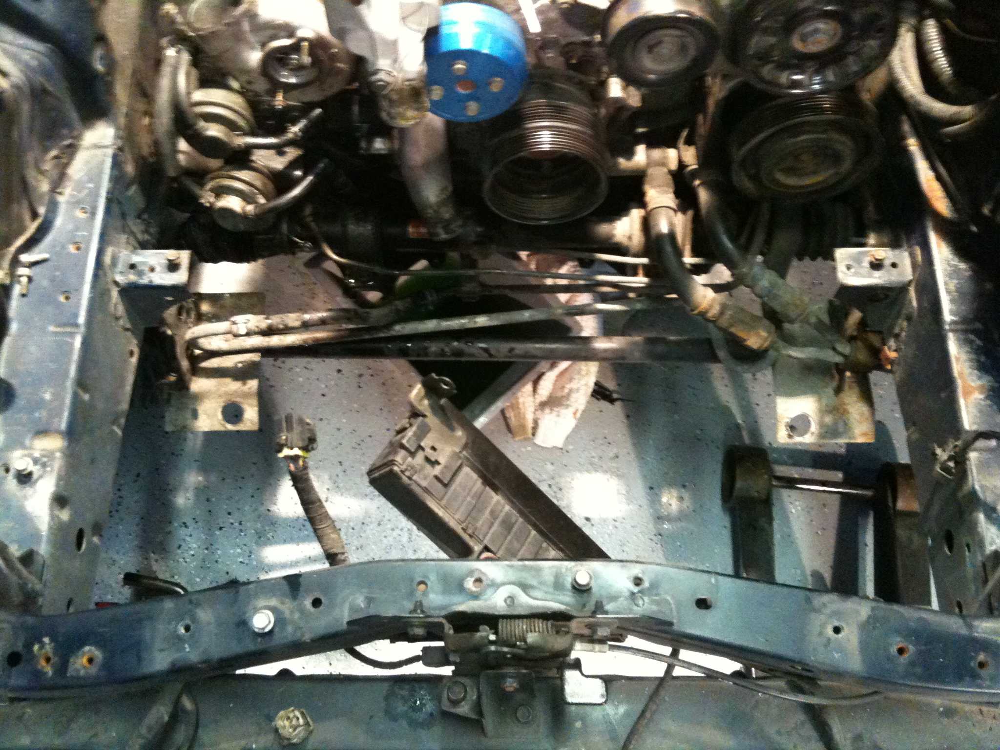
Start by recording the original pipe routing and photographing every connection. Label the front and rear circuits before loosening fittings. On many systems, the ABS modulator sits between the master cylinder and calipers, so deleting it requires new hard lines or carefully planned replacement plumbing.
Use brake tubing, fittings and flare types suited to the vehicle. Do not mix metric and imperial threads, and do not assume a fitting is correct because it appears to screw in by hand. Copper-nickel tubing may be easier to form than steel, but it must still be correctly flared, clipped and protected from heat, suspension movement and sharp edges.
The bias valve should be mounted where it cannot be knocked accidentally, while remaining accessible for deliberate adjustment. A cabin-mounted lever is convenient for a competition car, but it needs a secure bracket and a clear operating position. Keep all hydraulic connections away from the turbocharger, downpipe and steering shaft.
Choosing A Bias And Master Cylinder Strategy
A manual proportioning valve normally reduces pressure to the rear brakes as line pressure rises. It does not increase rear pressure, correct an incorrectly sized master cylinder or compensate for poor pad selection. The target is stable braking with the rear axle approaching lock slightly after the front axle under the intended load conditions.
| Setup | Main advantage | Main risk | Typical application |
|---|---|---|---|
| Factory ABS retained | Best all-round stability and safety systems | More components and possible ageing faults | Road and mixed-use RX-7 |
| ABS removed, fixed proportioning | Simple and consistent plumbing | May suit only one load and tyre combination | Dedicated track car with known setup |
| ABS removed, adjustable valve | Allows circuit and weather tuning | Incorrect adjustment can cause rear lock | Competition or test-focused car |
| Dual-master pedal box | Broad adjustment range and strong motorsport control | Complex, costly and generally unsuitable for road use | Purpose-built race car |
Master-cylinder bore affects pedal travel and hydraulic force. A larger bore can shorten pedal travel but increase pedal effort; a smaller bore can provide more leverage and travel. Changing calipers, pad compounds, rotor sizes or tyre grip at the same time makes diagnosis difficult, so alter one major variable at a time.
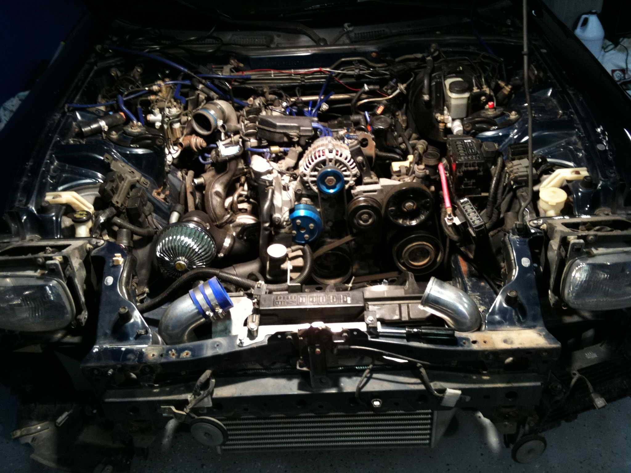
For a turbocharged FD, braking performance should be considered alongside heat management. The cooling requirements discussed in FD3S cooling upgrades are not a substitute for brake ducting, but they highlight how engine-bay heat and airflow can affect a hard-used car.
Installing The Replacement Circuit
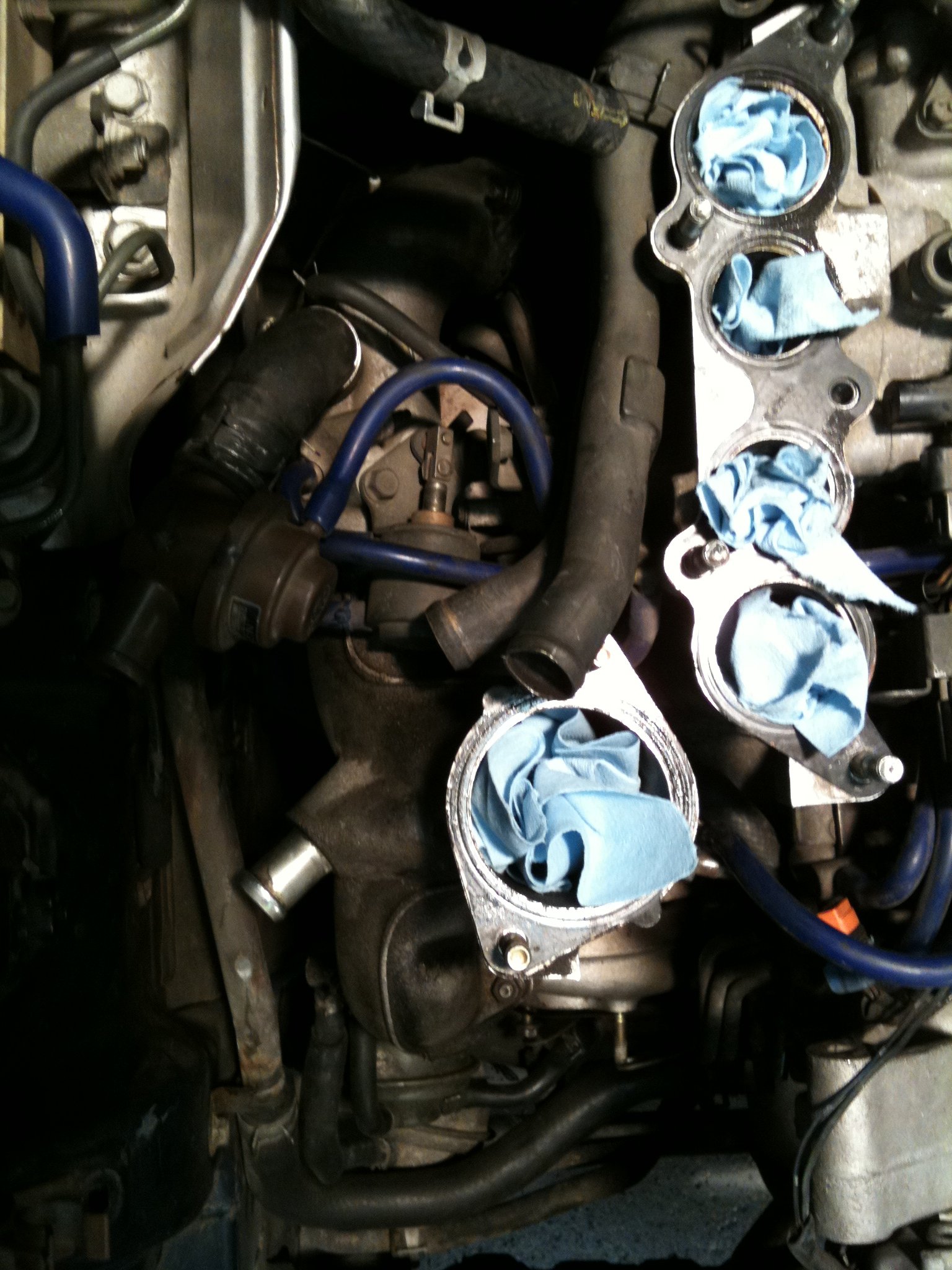
Support the car securely, remove the battery connection and drain the old fluid into a suitable container. Protect painted surfaces because brake fluid damages paint quickly. Once the ABS unit is removed, cap open ports while working and prevent dirt from entering the master cylinder or calipers.
Form the new lines with smooth bends and adequate clearance. Avoid tight kinks, unsupported spans and contact with bodywork. Secure the tubing with proper clips, leaving enough movement at suspension and steering components without allowing the line to rub. Use new sealing washers where specified and torque fittings according to reliable service information.
After assembly, fill with the correct fluid and bleed from the circuit furthest from the master cylinder, following the chosen system’s routing. Pressure bleeding can help, but a firm pedal after bleeding does not prove that the bias is safe. Inspect every joint under pressure and check for seepage after the car has been stationary overnight.
Setting Bias With Controlled Testing
Begin with the bias valve in a conservative position that gives the front brakes priority. Test in a controlled area at low speed, then progressively increase braking force. The goal is to identify which axle locks first without putting other drivers, pedestrians or property at risk. A closed circuit and an experienced spotter are preferable to public-road testing.
Tyre temperature, fuel load, passenger weight and track conditions all influence the result. A setting that works at Sydney Motorsport Park on warm semi-slicks may be unsuitable on cold road tyres in the rain. Record the valve position, tyre pressures and symptoms in a notebook so changes are repeatable.
Checks before the first hard stop:
- Confirm pedal firmness and fluid level
- Inspect every flare, hose and mounting clip
- Verify wheels rotate freely with no hose strain
- Check warning lights and electrical connections
Symptoms that require stopping:
- Rear wheels lock before the fronts
- The car changes direction under braking
- Pedal travel increases between tests
- Fluid appears around any fitting
Completing The Job Responsibly
Brake testing should continue after the initial installation. Recheck fittings, line clearance, pad seating and rotor condition after the first session. Inspect the system whenever the car is serviced, especially after kerb strikes, gravel excursions or transport on a trailer. Keep the original ABS components labelled if there is any chance the car will return to road specification.
An adjustable valve is a tuning tool, not a shortcut around proper suspension geometry, matched tyres or suitable pads. Owners comparing rotor and housing choices for wider RX-7 projects may find the Nikasil and iron liner debate useful as a reminder that material and operating conditions matter throughout a build. Brake decisions deserve the same careful reasoning.
If the car uses an aftermarket ECU, keep brake-system work separate from engine calibration. Resources on PowerFC tuning are valuable for engine management, but electronic tuning cannot correct a hydraulic bias problem. Have the finished installation inspected and brake-tested by a qualified professional before returning the RX-7 to Australian roads or entering competition.