
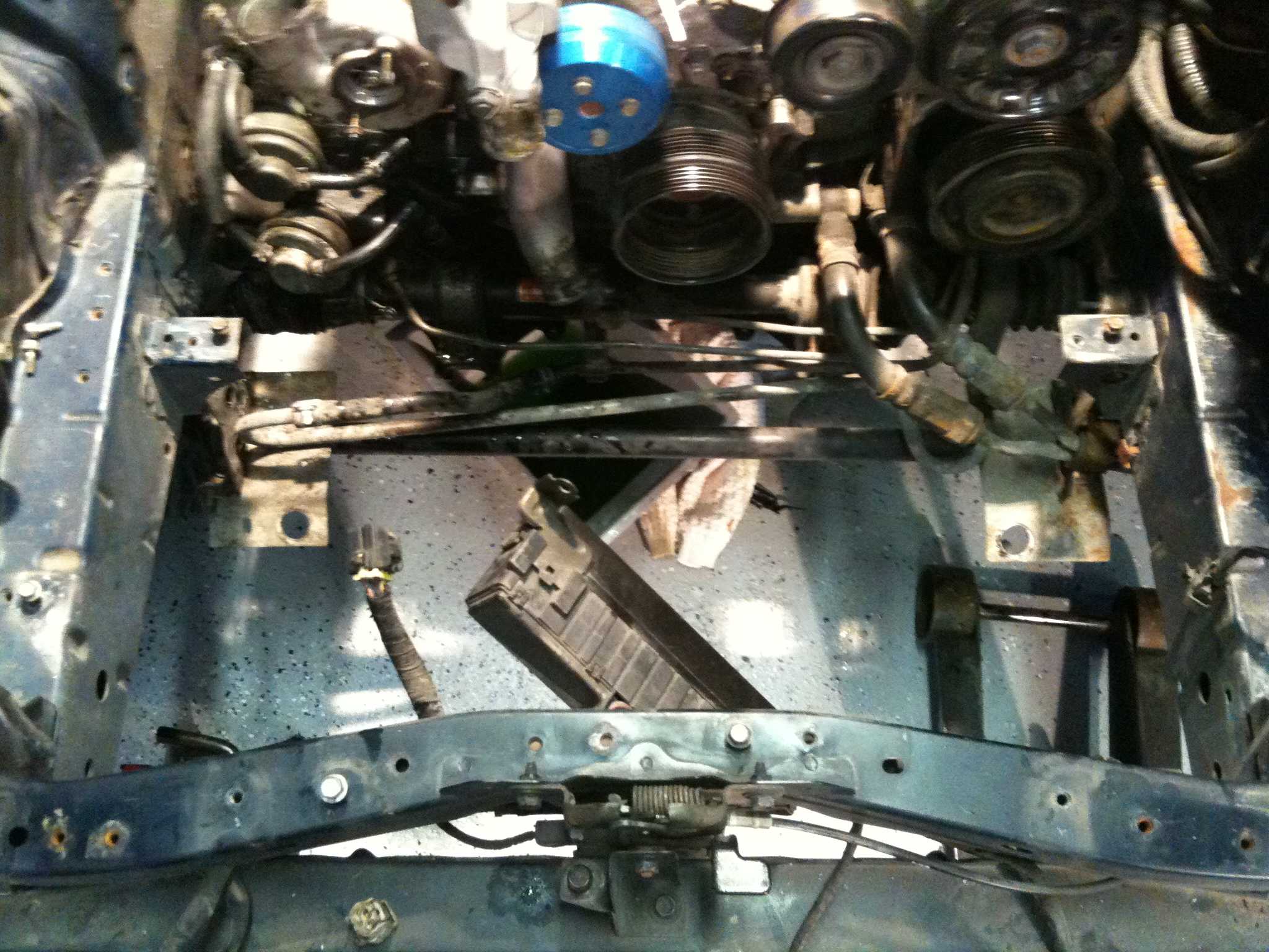
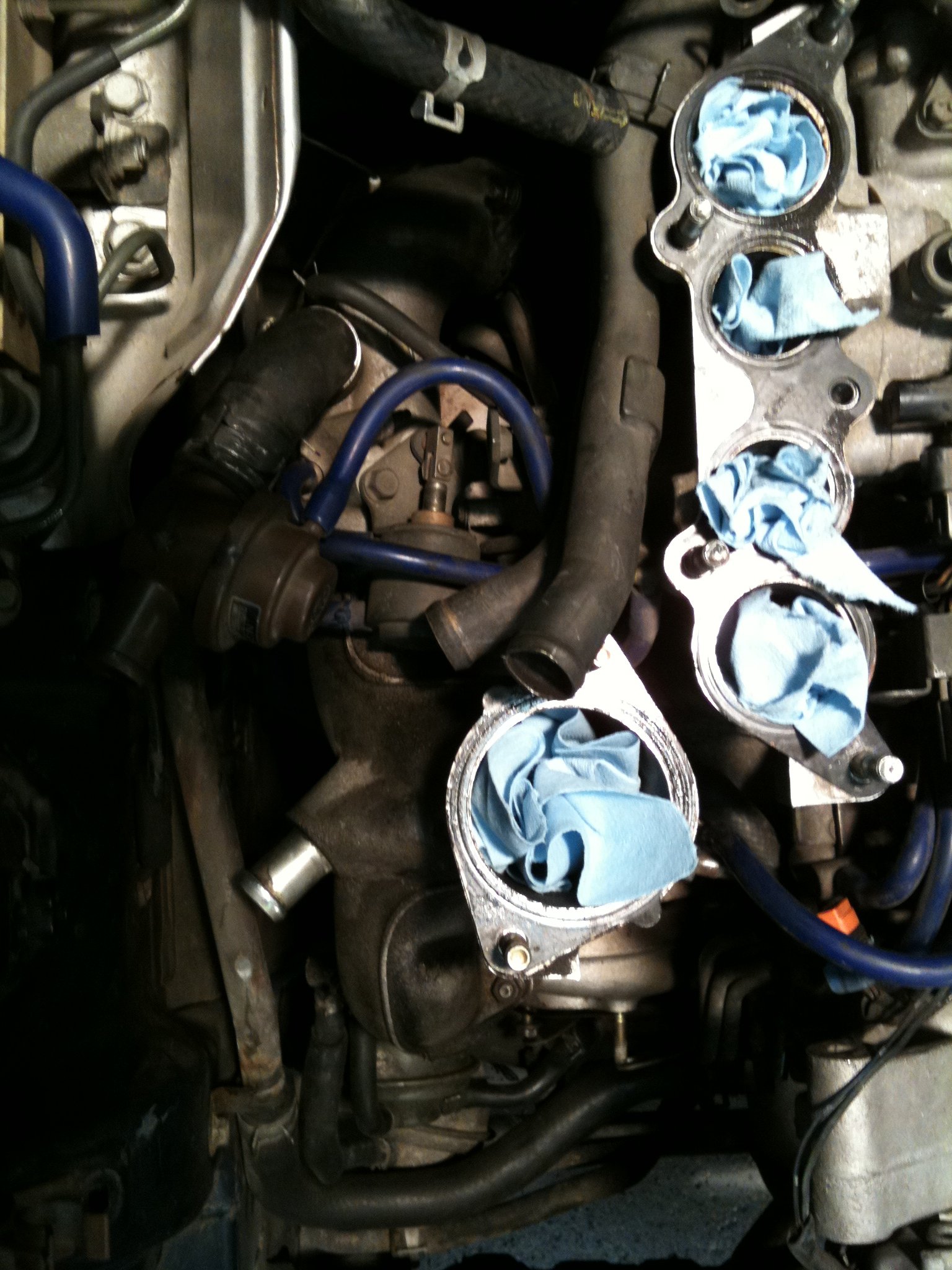
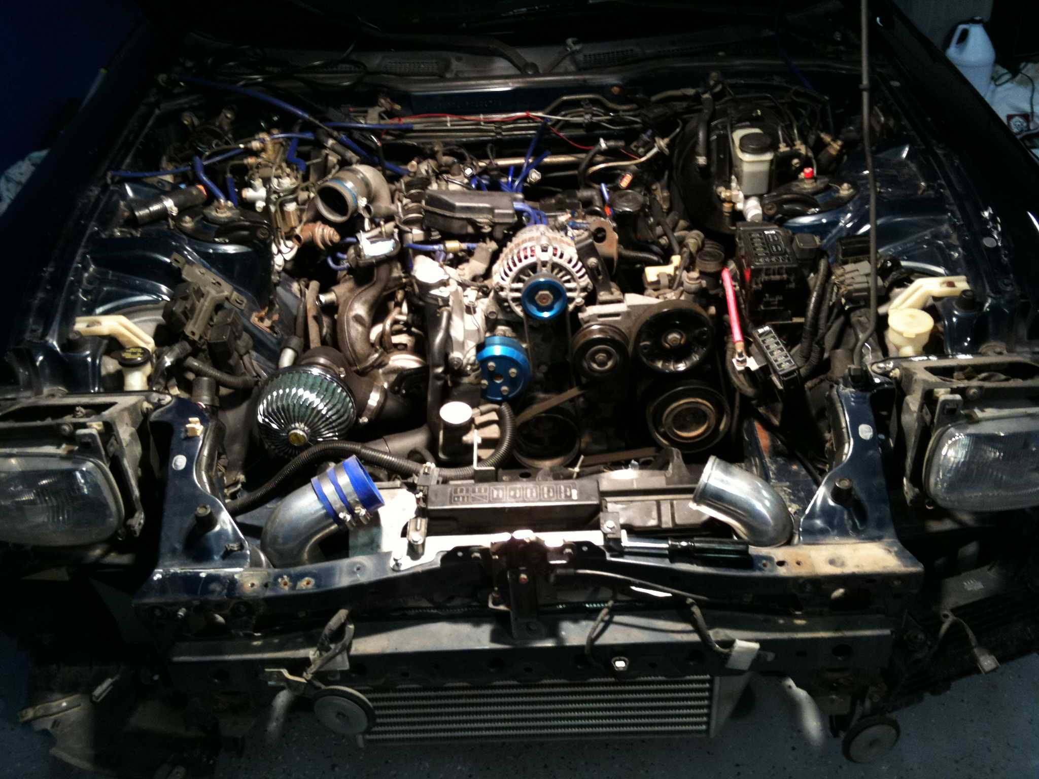
RX-7 exhaust system architecture: factory vs aftermarket flow paths
An RX-7’s exhaust is part of its operating envelope, not merely a box at the back of the car. On a rotary engine, primary pipe length, collector design and the way the turbocharger is matched shape the exhaust pulse and the backpressure the engine experiences under load. Factory systems balance those needs with noise control, heat shielding and, on some cars, emissions equipment.
Replacing it can improve flow and flexibility, but removing a resonator or fitting a larger pipe does not automatically create more usable power. The useful comparison follows the gas from the exhaust ports through the turbine housing and downpipe to the tailpipe, then checks whether each change suits the engine, turbo and chassis.
Reading the factory flow path
On a turbocharged 13B, the exhaust ports feed manifold primaries, which merge into the turbine housing. Turbine discharge then runs through the downpipe toward the catalyst, resonator and silencer, with the arrangement varying by model year and market. Carburetted 12A cars and some 13B variants use different upstream layouts, so a generic RX-7 diagram can mislead.
TurboRX7’s production specifications and service manuals help establish what was originally fitted, including catalyst location and silencer configuration. For a modified car, the under-bonnet clues are worth checking before ordering anything: this guide to factory turbo identification offers a practical cross-check when badges, bodywork or engine-bay details no longer tell the whole story.
What aftermarket flow changes
Three common upgrade boundaries describe most projects. A cat-back system keeps the manifold, downpipe and catalyst while replacing the rear silencer and tailpipe. A mid-pipe changes the path between the turbine outlet and rear silencer. A full system replaces nearly everything downstream of the exhaust ports, including the manifold and turbo flange.
Bigger is not automatically better. A wider downpipe may reduce restriction in a high-flow application, while a collector that handles the rotary’s pulses well can matter more than a nominal diameter increase. Straight pipe can lower backpressure and sharpen response, but it also increases exhaust noise and heat around the rear of the car.
Straight-through silencers are often described as unrestricted, yet their cores still vary in restriction. Factory-style resonator and silencer combinations are tuned to cancel particular frequencies; changing their internal volume can alter drone as much as it changes airflow. The best target is the engine’s operating range, rather than the largest pipe available.
Why primary and collector geometry matter
Rotary engines produce a strong, regular exhaust pulse, making scavenging sensitive to the manifold’s internal volume and primary lengths. Porting the exhaust ports or changing the runners may improve high-rpm gas exchange, but overly long or mismatched tubes can delay the turbo’s response. Collector merge angle then determines how evenly the flow reaches the turbine inlet.
The turbine housing and wastegate must be matched to the new flow path. A larger turbine generally promotes top-end breathing at the cost of earlier boost, while a smaller one may respond sooner but restrict high-rpm output. On a 13B conversion, the exhaust manifold, turbine housing and wastegate form a connected design; changing only the pipe behind them can create a poor match.
Resonators, silencers and Australian road realities
A factory resonator is an acoustic tool, not a deliberate obstruction. Its volume and internal shape tame pulses from the primaries and turbine, producing the low hum associated with a healthy stock RX-7. Removing it may reveal a sharper note from the remaining silencer, so listen to the complete system rather than judging one pipe in isolation.
Australian ownership adds practical considerations. Right-hand-drive layouts still need exhaust clearance around fuel tanks, body brackets and underbody structure. A hot pipe running beside bodywork during a Melbourne summer is a different proposition from the same car during a winter run to the Victorian snowfields. Exhaust heat shields and correct hangers protect nearby components as well as people working underneath the car.
Long arvo runs through regional Victoria or western NSW make a resonant buzz obvious, as there is less traffic to mask it. Exhaust noise and vehicle modification requirements vary between states, so check the current road rules before using a louder car on public roads. Parts often arrive through specialist Australian suppliers or international freight from Japan and North America, making common sizes and available hardware practical advantages.
Configurations that need special care
Single-turbo and sequential-turbo cars, 13B and 20B engines, and converted non-turbo body shells should each be treated as separate layouts. A 20B’s higher-flow exhaust demand can justify a different downpipe and collector from an older 13B, while a factory turbo system converted to naturally aspirated running needs a complete replacement path rather than a reused rear section.
Sensors and emissions hardware deserve particular attention. Removing a catalyst or pre-cat oxygen sensor can trigger a fault on some engine-management systems and may affect fuelling corrections. Compare part numbers, fitting points and sensor positions rather than assuming the badge identifies pipe sizes. The ECU, fuel system and ignition must also support any airflow increase.
Building and verifying a safe upgrade
Start by documenting the factory route: photograph every section, record casting numbers and retain the original flanges and hangers. A service-manual diagram can then be marked against what is actually fitted. For a full-system build, new gaskets, correct fasteners, an oxygen-sensor bung and secure exhaust mounts are basic requirements, not finishing extras.
TurboRX7’s wider archive contains unrelated material, including a page on Elvis Frog bonus codes, alongside its technical library. The relevant mechanical references are the model-specific diagrams, production specifications and service manuals; those are the documents to use when confirming pipe sizes and original equipment.
After installation, check for leaks, verify sensor readings and monitor exhaust-gas temperature, fuel trims and oil pressure under load. A workshop with a dyno or suitable data logger can reveal whether the new flow path has delivered a repeatable gain. If the result is only noise, revisit primary geometry, collector design and turbo matching rather than ordering an even larger silencer.
Use TurboRX7’s diagrams and identification guides to map your car’s exhaust from the manifold to the tailpipe, then choose a system suited to its engine and intended use. Record the factory configuration before removing anything, and verify boost, fuelling and heat management on a workshop dyno before taking the car onto the road.