
Stock Twin Sequential Turbo System: Operation And Common Failures
The Mazda RX-7 FD’s stock twin sequential turbo system was designed to give the 13B-REW strong low-speed response without sacrificing high-rpm airflow. Rather than running both turbochargers in the same way across the rev range, Mazda used a network of valves, vacuum actuators and electronic solenoids to bring the second turbocharger into the boost circuit progressively.
That arrangement delivers the characteristic surge many owners describe as the “second kick”, but it also creates several failure points. Age, heat, brittle vacuum hoses, neglected cooling systems and previous modifications can make a healthy-looking FD feel flat or unpredictable. For Australian owners, summer temperatures and long highway pulls can expose weaknesses that remain hidden during a short workshop test.
What The Factory System Is Designed To Do
The 13B-REW uses two similarly sized turbochargers arranged in a staged, sequential layout. At low engine speed, the primary turbocharger provides most of the boost, while exhaust and intake control valves keep the secondary turbocharger from contributing fully. This helps the engine build torque quickly without asking both turbines to operate inefficiently at low flow.
As engine speed and load rise, the control system gradually prepares the secondary turbocharger. Exhaust gas is directed through it to increase turbine speed, then the intake side is opened so compressed air from the second unit can join the charge system. When everything works correctly, the transition feels progressive rather than like a sudden power switch.
The design is specific to the FD’s 13B-REW packaging and calibration. The 20B production history also helps explain how Mazda developed its later rotary turbocharging systems around compact packaging, staged airflow and high exhaust temperatures.
How The Sequential Changeover Works
During the early part of the rev range, the primary turbocharger supplies boost and the secondary turbo is effectively being brought up to speed. A pre-spool phase uses exhaust flow and control valves to reduce the delay before the second turbo joins in. The exact changeover point varies with throttle position, engine load, boost pressure and ECU strategy, so it should not be treated as a single fixed rpm figure.
At the transition, the exhaust gas control valve and intake air control valve change position in a carefully timed sequence. The secondary turbocharger first receives enough exhaust energy to accelerate, then its compressor outlet is connected to the intake path. If the timing is wrong, the engine can hesitate, surge, or produce a hollow dip before the second turbo contributes.
A standard FD therefore needs more than two functioning turbochargers. It needs correctly routed hoses, responsive actuators, sound solenoid valves, accurate sensors and an ECU that can see plausible operating conditions. A fault in any part of that chain can imitate a worn turbocharger.
Vacuum, Valves And Control Hardware
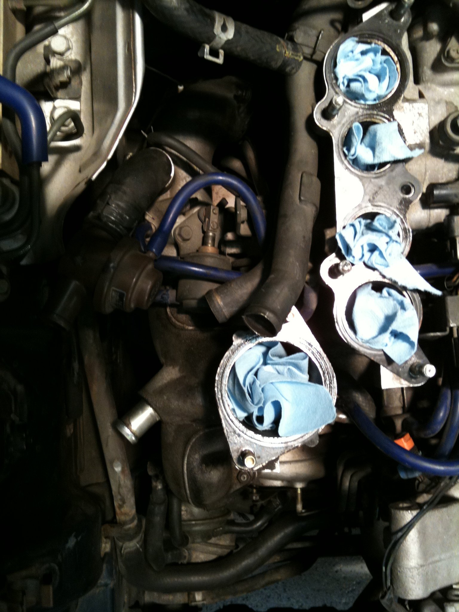
Small vacuum lines operate several important actuators, including the turbo control valves and wastegate mechanisms. These hoses become hard and cracked with age, especially around the rear of the engine bay where radiant heat is severe. A line connected to the wrong nipple can create symptoms just as serious as a split hose.
The vacuum switching valves, or VSVs, are electrically controlled by the ECU and use engine vacuum to move the mechanical components. Sticking valves, corroded connectors and weak vacuum supply can prevent pre-spool or leave a control flap partly open. A useful first inspection is to compare every hose with a reliable factory diagram rather than trusting a previous owner’s colour coding.
| Area | Normal role | Typical failure symptom |
|---|---|---|
| Primary turbocharger | Provides initial boost | Slow response, oil smoke or low boost |
| Secondary turbocharger | Adds airflow at higher load | Flat transition or no high-rpm power |
| Exhaust control valves | Manage turbine energy | Hesitation, boost instability |
| Intake control valve | Brings secondary compressor online | Secondary turbo fails to contribute |
| VSVs and vacuum hoses | Command actuator movement | Intermittent or inconsistent changeover |
| Wastegates | Limit boost pressure | Overboost, boost creep or weak boost |
Symptoms That Point To A Fault
A clean, repeatable pull should build boost smoothly, with a noticeable increase in acceleration as the secondary turbocharger joins the system. A sharp stumble around the changeover range often indicates a control problem rather than an immediately destroyed turbo. Surging can point to unstable valve operation, an intake leak, or compressor flow being disturbed by an incorrectly fitted aftermarket component.
Low boost across the whole rev range deserves a wider inspection. Leaking intercooler couplers, split intake pipes, loose hose clamps and damaged vacuum lines are common causes. Blue smoke, excessive shaft play, metallic noise or oil pooling in the compressor plumbing suggest a turbocharger problem, although rotary engine oil carryover must also be considered.
Australian cars may show these faults after repeated hot-weather use in western Sydney, Brisbane or Perth. Heat soak after stop-start traffic can soften couplers and expose marginal cooling or electrical components. A car that feels fine on a cool morning may lose consistency during a summer drive or a long run through the Adelaide Hills.
Common Mechanical And Control Failures
The turbocharger oil and water lines should be checked carefully. Restricted oil supply can damage bearings, while blocked or poorly routed coolant lines increase thermal stress after shutdown. Many imported FDs have spent years in modified form, so braided lines, deleted emissions equipment and unfamiliar boost controllers require close inspection against the original layout.
Wastegate actuators can become stiff, and their hoses can leak before the actuator itself fails. A stuck-open valve causes weak boost; a stuck-closed or poorly controlled valve can produce dangerous overboost. The factory boost-control arrangement is complex enough that removing components without understanding their purpose often creates a new fault.
Porting and exhaust changes also affect sequential behaviour. A bridgeport, peripheral port or aggressive street port alters exhaust pulse energy and low-speed airflow, so the original changeover calibration may no longer suit the engine. The differences are outlined in this guide to 13B porting choices, which is useful before blaming the turbo system for every drivability issue.
Testing Without Guesswork
Begin with a visual inspection and a pressure test of the intake tract. Check the intercooler, throttle-body coupler, bypass plumbing and every small vacuum hose. A smoke test can reveal leaks that remain invisible during a quick rev in the driveway.
Use a hand vacuum pump to confirm that each actuator moves smoothly and holds vacuum. Electrical testing should verify VSV resistance, connector condition and ECU command signals. Boost should be logged under controlled conditions rather than judged by an old dashboard gauge, and fuel pressure, air-fuel ratio and ignition timing should be monitored during any high-load test.
Factory manuals, wiring diagrams and rotary reference material collected by TurboRX7 technical resources can help separate a genuine turbocharger failure from a hose-routing or control-system fault. For a road-registered car in Australia, testing on a reputable dyno is safer than repeated full-throttle runs on public roads.
Repair Priorities For Australian Owners
Restore the factory plumbing before fitting a larger turbo, electronic boost controller or unusual vacuum arrangement. Replace brittle hoses with correctly sized heat-resistant lines, renew suspect couplers and ensure the intercooler system is sealed. The best repair is often a careful return to standard operation, particularly for an imported FD with an unknown history.
Use suitable fuel for the calibration. Premium 98 RON is widely available in Australian cities and along major routes, while E10 should not be treated as an automatic substitute for a tuned rotary. Cooling system condition matters equally: clean radiators, functional fans, sound water seals and correct coolant reduce the risk of detonation and heat-related control problems.
Before a road trip from Melbourne to Canberra or a spirited run near the Gold Coast, verify boost control, oil level, coolant temperature and intake leaks. Keep records of vacuum routing and test results, then have the car checked by a rotary-experienced workshop or dyno operator. Use the factory system as a baseline, diagnose each control component methodically, and repair the cause before chasing more power.