
Suspension geometry basics for the FD3S
FD3S suspension geometry comes down to three relationships between each wheel and the road. Camber controls tyre lean, caster shapes steering response, and toe sets whether wheels point in or out. Coordinated values improve predictability; excessive or uneven angles increase wear, wander and instability.
Australian ownership adds context. Left-hand traffic makes steering effort and turn-in relevant on roundabouts, while the market is dominated by imported right-hand-drive cars. Retain customs paperwork, confirm ADR and state registration requirements, and record previous suspension work before altering alignment.
Daily use spans Sydney stop-start traffic, Melbourne tram corridors, humid Brisbane streets and rougher regional roads. Tyres, ride height and road roughness affect the result, so the target is a setup that stays stable under braking, follows the road through corners and feels composed after highway driving.
Reading the three main angles
From the front, camber is wheel lean. From the side, caster is the fore-and-aft inclination of the steering axis. From above, toe describes whether a wheel points inward or outward. Scrub radius, camber thrust and included toe angle explain why small changes can alter the FD3S’s behaviour.
Factory figures are not a universal recipe. Ride height, dampers, springs, tyre width, wear and market differences can shift original geometry, so use workshop data for the exact chassis and compare it with the measured car. The TurboRX7 reference library offers manuals, production specifications and model-specific information.
Camber and tyre contact
Negative camber, with the wheel’s top leaning inward, helps an outside tyre remain better aligned as the body rolls, increasing usable lateral grip. Rear camber also supports rollover stability, although it is generally less adjustable. Tyre width, body roll and uneven terrain can shift the loaded wheel away from its ideal angle.
Too much negative camber reduces the outside tyre’s straight-road contact patch, braking and traction, and often wears the inside shoulder. Unequal left-right camber creates lateral bias. On a street FD3S, restore the specified ride height and suspension condition before judging the reading rather than using an extreme alignment.
Caster, toe and stability
Positive caster lets the wheel self-centre as it follows a bump, reducing wander and strengthening the car’s return to straight ahead. Too little can make the front end feel vague, while excessive caster increases steering effort and can add kickback through potholes. Bump steer appears when suspension movement changes caster or toe away from the centred position.
Front toe-in usually supports straight-line stability; toe-out can improve initial turn-in when both front wheels are balanced correctly. Rear toe is equally important because it controls the rear axle’s tracking. Total toe across an axle, individual toe and thrust angle matter more than quoting one wheel’s number in isolation.
| Angle | Main effect | Stable street tendency | Warning sign |
|---|---|---|---|
| Camber | Controls tyre lean during body roll | Modest negative camber at the specified ride height | Inner-edge wear and reduced straight-line grip |
| Caster | Controls steering return and stability | Positive caster | Wandering when low; kickback and effort when high |
| Toe | Controls each axle’s tracking | Slight front toe-in with coordinated rear toe | Constant correction, instability or conflicting turn-in |
Treat these values as handling directions, not targets to copy. An FD3S should track straight without constant correction yet remain responsive when the driver asks for a turn. If front and rear settings fight each other, the alignment may be numerically plausible while the complete chassis feels unsettled.
Preparing the car for alignment
Preparation determines whether an alignment will hold. Set the tyres to the pressures on the driver’s door placard, verify ride height on level ground, inspect tyre size and condition, and settle the suspension by rolling the car and completing a short road test. Marking a strut or wheel-position indicator before jacking the car reveals whether a bent component is pulling the wheel out of position. A technician will normally set camber first, then caster and toe, while coordinating the rear axle.
Check ball joints, tie-rod ends, anti-roll-bar links, spring seats, strut bearings and control-arm or toe-link bushings first. Play or corrosion can shift an angle after adjustment. Roadworthiness is separate: this New Jersey-focused explanation of windshield damage causes helps identify impact-related glass damage, but Australian repair and inspection rules remain the relevant standard.
Recognising geometry-related problems
Inside-edge wear suggests excessive negative camber or a heavily rolled chassis; outside-edge wear can result from too much positive camber, worn dampers or alignment that is wrong for the road. Cupping may indicate shock damage, severe bump steer or an out-of-round tyre. One-sided wear deserves a geometry and mechanical inspection, not a quick pressure increase.
Pulling to one side can come from unequal camber or caster, a shifted tyre, low pressure or a steering or suspension fault. Wandering and poor straight-line stability often point to too little caster or incorrect total toe. Australian workshops handling Japanese imports should inspect the whole assembly and use an alignment printout, because replacing a compliant RX-7 bushing with an incorrect part can move the axle as well as spoil the ride.
Building a usable street setup
Build the alignment around the car’s use. A quiet touring setup needs modest negative camber, positive caster and stable toe for clean highway tracking; a more responsive setup may use additional front camber and controlled rear toe, provided tyre clearance, ride height and the road surface support it. Any angle that causes instability on wet Australian roads is too aggressive.
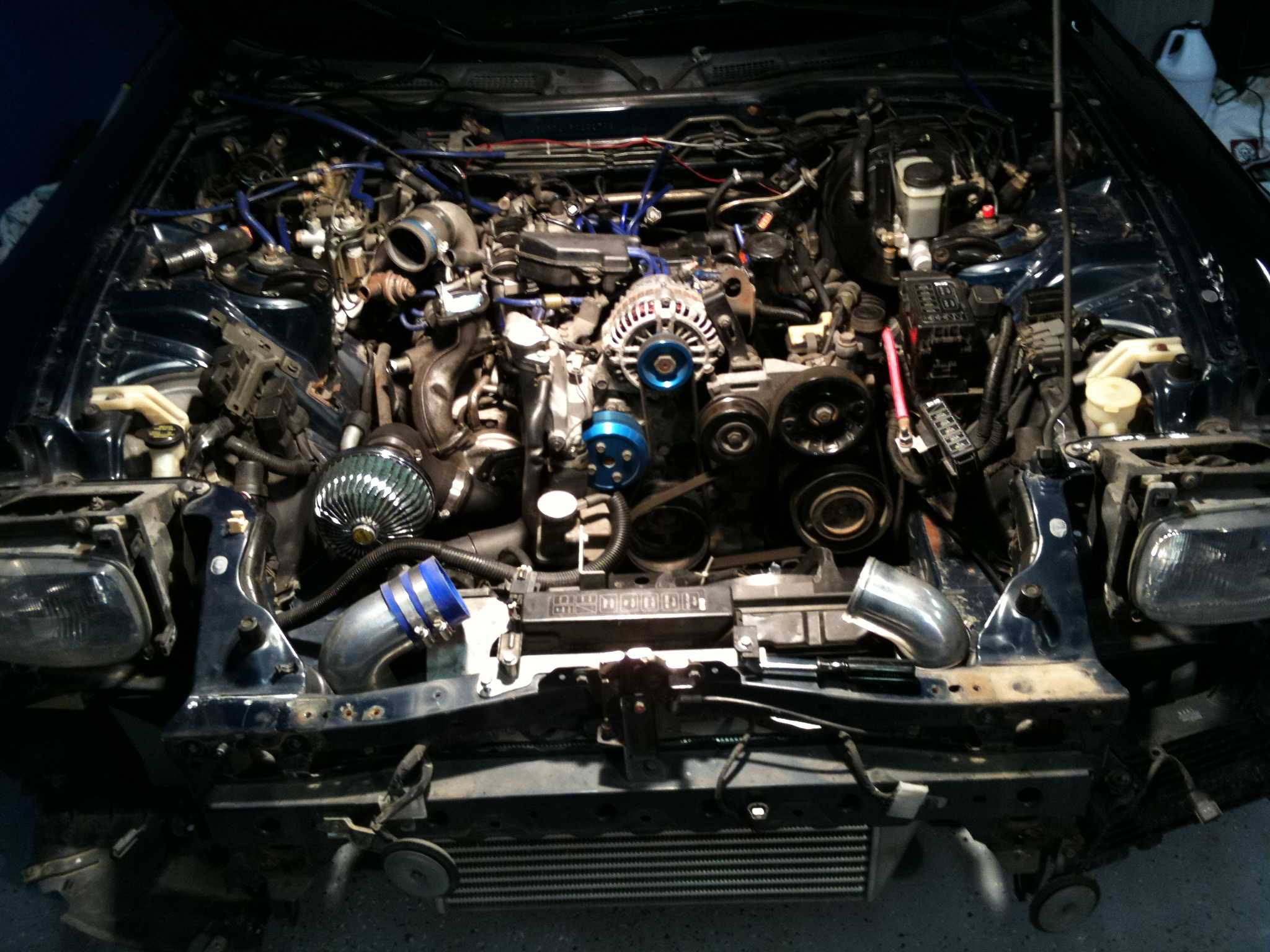
Record the alignment after every spring, damper, subframe or steering change. If the same workshop visit includes engine-bay work, keep packaging in the job sheet: the site’s radiator and ducting guide covers cooling upgrades, but thermal packaging still requires a fresh ride-height and geometry check. Local tyre availability and workshop expertise should influence parts choices, not force the chassis to compensate for the wrong component.
Start with a baseline inspection, obtain the correct factory geometry data and request a printed before-and-after report covering ride height, individual camber, caster, individual toe and total toe. Road-test the car over a familiar route, then recheck any reading that produces pull, wander or steering that will not settle.
Book a qualified local alignment technician familiar with the FD3S, keep the settings with the car’s records and remeasure after major suspension work. That repeatable baseline gives the rotary chassis the clearest path to balanced handling while preserving tyre life and everyday usability.