
Replacing the FC3S Ignitor and Coil Cables
An FC3S uses a distributor-driven ignition system, but its working parts are spread across the engine bay: an ignition coil, a semiconductor igniter, high-tension leads and a multi-pin loom connection. Replacing the ignitor and coil cables is a manageable job when the correct pieces are identified before the bay is dismantled.
The igniter controls current through the coil’s primary winding; the coil then produces the high voltage carried to the spark plugs by the coil cables. Worn insulation, heat-damaged connectors or a failing module can therefore produce a no-start, intermittent misfire or a fault that appears only when the engine is hot.
This guide covers the FC3S rotary ignition layout, parts identification, access, replacement and proving the repair. It applies to Australian-owned cars with genuine 13B or 13B-MSP installations while recognising modifications made by previous owners.
Work methodically and use the correct service information for the vehicle’s year and specification. A sensible order is to document the existing system, disconnect the battery safely, replace the cables, fit the igniter, then test the complete circuit before returning the car to the road.
Mapping the ignition components
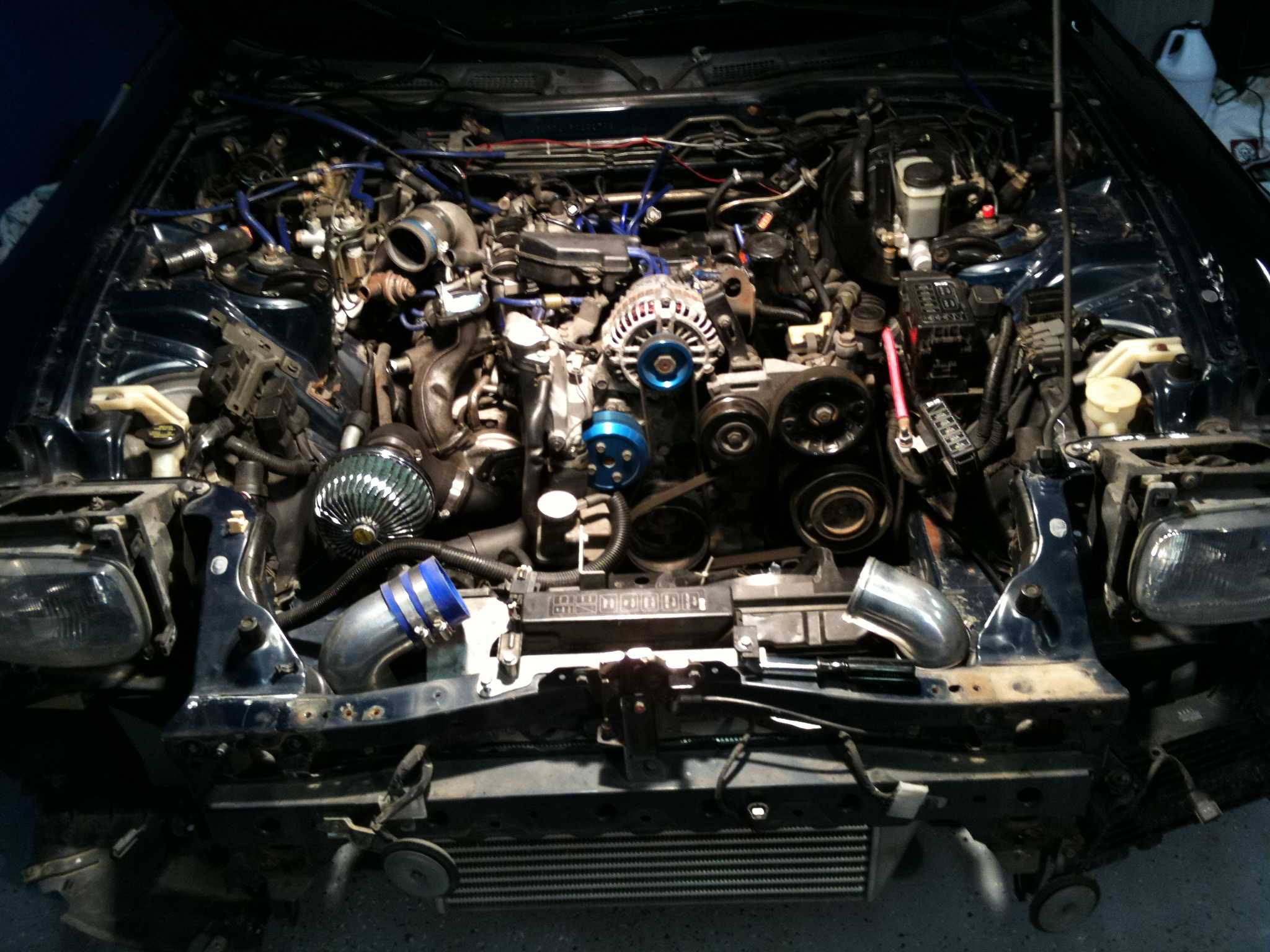
The factory layout groups the coil and igniter around the distributor. High-tension leads run from the coil to four distributor-cap terminals and onwards to the spark plugs, while the engine management system uses distributor signals to coordinate ignition timing.
The factory information library is useful for confirming original equipment and early-versus-late details. Distinguish the coil-to-plug cables from the lower-voltage coil-to-igniter lead, and treat the loom plug as a separate item. It is a poor choice to order a generic RX-7 ignition loom for an FC3S.
Identifying compatible replacement parts
Record the coil, igniter and distributor part numbers, then compare them with the catalogue for that model year. Several igniter and coil designs appeared across the FC3S production run, and engine swaps can introduce another arrangement. Match connector housings, cable lengths, terminal orientation and mounting points rather than relying on external appearance.
For additional connector identification, Narmadi diagrams can help with layouts and fasteners. Use them alongside the relevant manual, not instead of it. A replacement lead set should reach every cap tower without tension and remain clear of the intake, exhaust and steering components.
Preparing the engine bay safely
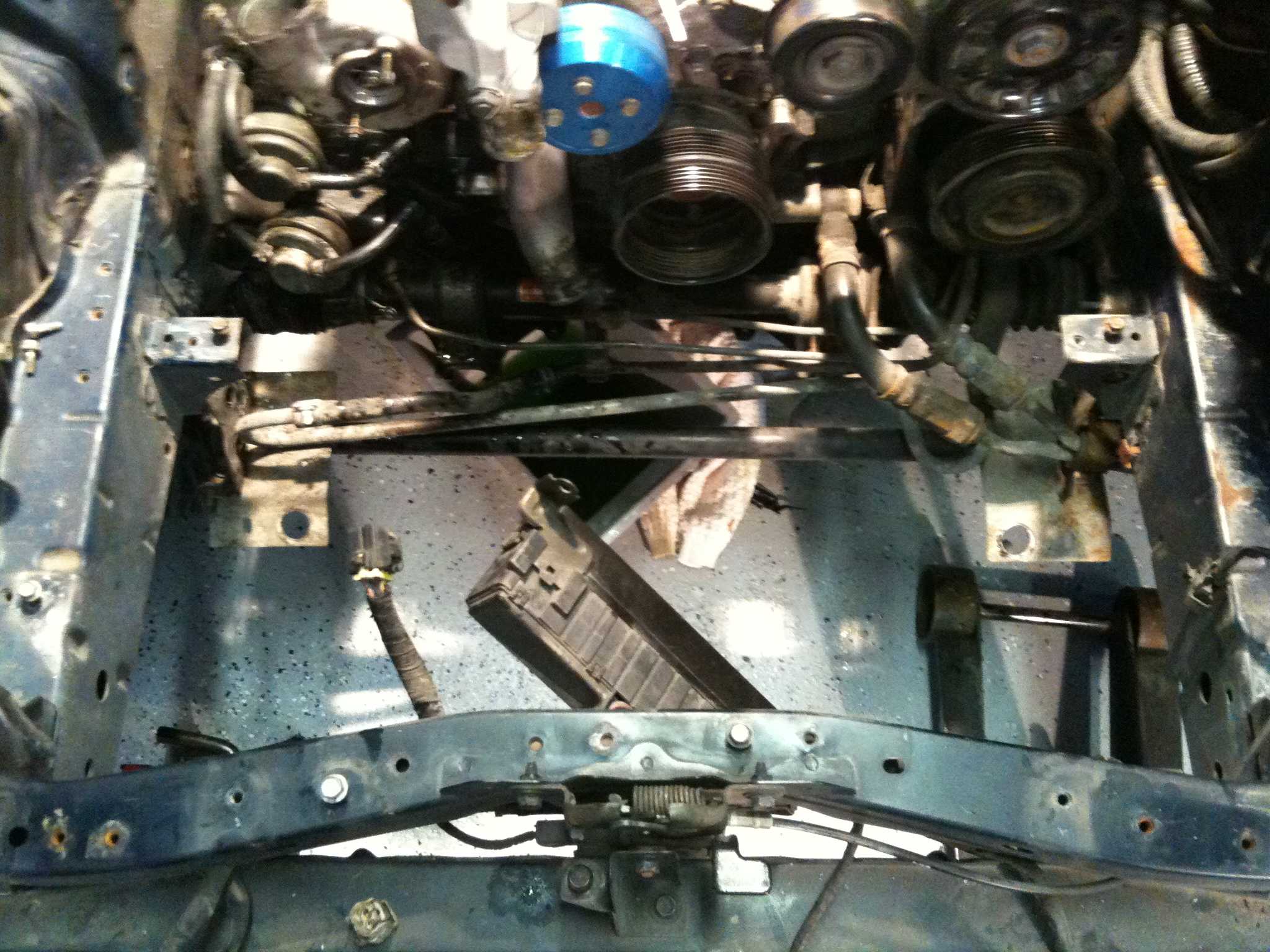
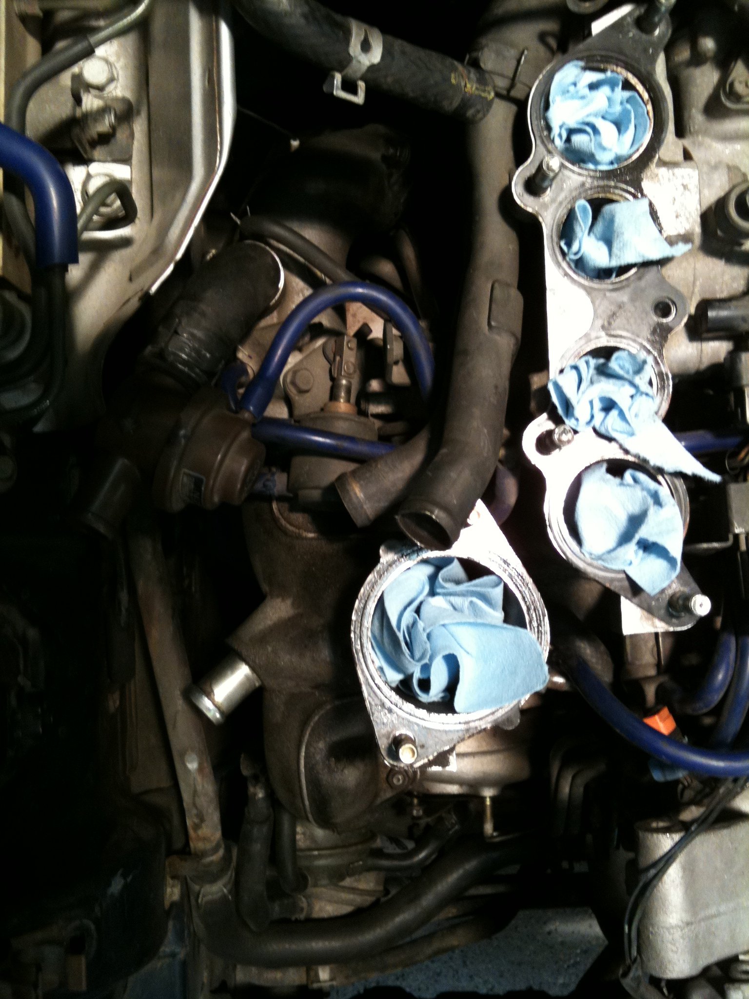
Allow the engine to cool, remove the battery’s negative terminal and insulate the cable. Photograph the original coil and igniter connections before unplugging anything, then label each connector. Remove only the airbox, intake ducting or trim needed for access, and retain every clip, seal and washer.
Handle the distributor cap carefully because aged plastic splits easily. Release its locking tabs without levering against the housing. Mark plug positions if the leads will be removed, keep the cap in a clean bag and inspect the towers for stretched or broken terminals.
Check each connection against its intended function before fitting new parts:
| Connection | Factory arrangement | Replacement check |
|---|---|---|
| High-tension coil leads | Four leads from coil to cap terminals | Correct length, secure boots and sound insulation |
| Coil-to-igniter lead | Carries the low-voltage primary-circuit connection | Correct terminal fit and no exposed strand |
| Igniter loom plug | Links the ignition wiring to the vehicle harness | Keyed housing, intact lock and seated terminals |
| Igniter mounting | Secures the module on its bracket or engine | Clean mating surfaces and firm fasteners |
Fitting the new cables and igniter
Fit the new coil cables one at a time, pressing each boot squarely onto the coil terminal and cap tower. Route them as the original set did, maintaining enough clearance for servicing and engine movement. Generic thick cable may not enter the cap boots, so match the original lead diameter and terminal construction where practical.
For the igniter, transfer any mounting bracket or earth connection exactly as supplied, clean the mating metal and secure the module without crushing its housing. Make plug connections fully home, inspect for bent pins and protect the loom from chafing. Follow the service manual for torque values and connector locking methods.
Proving the repaired ignition circuit
Reconnect the battery’s negative terminal and perform static checks before starting. Confirm that the new leads have no continuity to earth, that the igniter supply and earth paths are sound, and that every connector is properly seated. If the distributor was removed, reinstate the timing before running the engine.
Start the engine without boost and watch the tachometer closely. Listen for steady idle, check for warning lights and confirm normal throttle response. Vary the engine speed through its range, then inspect the leads, connectors and cap for arcing, discoloration or heat damage. Recheck the installation after a longer drive, when vibration and thermal cycling have exposed any weakness.
Sourcing parts and advice in Australia
Australian RX-7 buyers often combine local breakers and specialist suppliers with parts arriving from Japan. Imported ignition components may incur GST and customs duty, so check current Australian Border Force rules, obtain a clear invoice and describe the used part accurately.
The factory brochure archive provides period background on model equipment and market differences. Local clubs such as the Perth Mazda Rotary Club and Mazda Rotary Club of Queensland can assist with wiring history and hard-to-find parts; specialist suppliers in Sydney, Melbourne and Brisbane offer another avenue. Coastal salt, dust and high temperatures accelerate connector deterioration, so inspect the entire loom rather than replacing only a failed section.
Completing the first road test
Keep the old igniter and cables until the repair has passed a road test, but retain the packaging and part numbers for future reference. Record the lead routing, connector positions and any departure from factory specification in the car’s service history. That information will matter if the vehicle is inspected, sold or dismantled again.
Begin with a short suburban route, then undertake a longer run that reaches operating temperature. Check for misfires at steady speed, confirm stable charging and listen for unusual ticking from the distributor area. A repeated stutter, hot-soak starting problem or burnt connector should send the car back to diagnosis rather than prompting an increase in boost.
Save the relevant manual with the car’s records, document every connection, and make the first start a fully verified stage of the rebuild.