
Testing 13B-REW crank angle sensor output
A 13B-REW crank angle sensor (CAS) gives the ECU the crank-position reference needed to identify rotor phase, schedule ignition and keep engine management in sync. On the factory arrangement, the crank output is an alternating signal from a magnetic pickup rather than a steady 5-volt logic feed, so the correct meter mode matters.
Intermittent CAS operation can appear as a hard no-start, sudden loss of RPM or an engine that drops into a backup mode. Check the crank-position circuit whenever the tachometer stops during cranking, especially after loom, ignition or engine-bay work.
Before pulling the engine apart, make the test repeatable: charge the battery, record engine condition and capture the output while idling, revving and cranking. Sort out a flat battery first, because it can imitate a failed sensor and waste an afternoon.
Australian examples are commonly right-hand drive, and imported FDs need local rego and roadworthiness details checked, but the sensor logic is unchanged. Parts may come through eBay Australia, a specialist wrecker or a long wait from a Japanese auction, so match the sensor and connector before ordering.
Establish the test conditions
Use the factory wiring diagram for the exact FD and engine, then back-probe the CAS output at the ECU or sensor plug. Keep the reference earth consistent, use short leads and preferably a 10x oscilloscope probe. Check battery voltage at the ECU during cranking; the 13B’s high current can expose a marginal earth that looks fine at idle.
Several instruments can reveal different aspects of the signal.
| Check | What it reveals | Useful result | Limitation |
|---|---|---|---|
| Oscilloscope | Waveform, frequency and dropouts | Repeating trace whose frequency rises with RPM | Requires correct probe and reference earth |
| DMM in AC millivolts or true RMS | Signal strength | Non-zero reading that responds to speed | Cannot show waveform or reliably count pulses |
| DMM in DC mode | Average or biased voltage | May sit near zero for an AC signal | Poor pass-or-fail test |
| ECU scan or log | Engine-management interpretation | RPM and sync remain stable | Confirms the result, not the sensor alone |
Do not expect a passive magnetic pickup to show a useful DC voltage. A zero reading in DC mode proves little, and a conventional DMM’s AC mode may under-read changing frequencies. Use the exact vehicle’s service manual as the authority; Narmadi technical material can support a broader wiring check.
Measure the live waveform
With the scope connected, look for a smooth, repeating waveform whose frequency rises with crankshaft speed. Peaks should remain even through a rev sweep, with no flat spots, missing bursts or sudden amplitude collapse. Several hundred millivolts peak-to-peak is plausible on an OEM installation, but the workshop manual’s limit is the benchmark.
Watch the trace during cranking as well as at idle. It may become less regular while the engine starts, but it must still correlate with crank movement. A signal that stays at a fixed frequency or disappears when RPM changes is not tracking the sensor. Keep the probe clear of the ignition leads.
A DMM in AC millivolts or true-RMS mode is a useful backup. Its reading should be non-zero and responsive to speed, although inexpensive meters may under-read changing frequencies. Never crank with the meter set to resistance, and do not use an ordinary DC voltage reading as a pass-or-fail test.
Check the sensor, wiring and trigger
With power removed, disconnect the sensor and compare its winding resistance with the service-manual range for that 13B-REW pickup. Keep the meter off the ECU and do not infer a failed sensor from a reading taken through the harness. Inspect the connector for corrosion, bent pins or moisture.
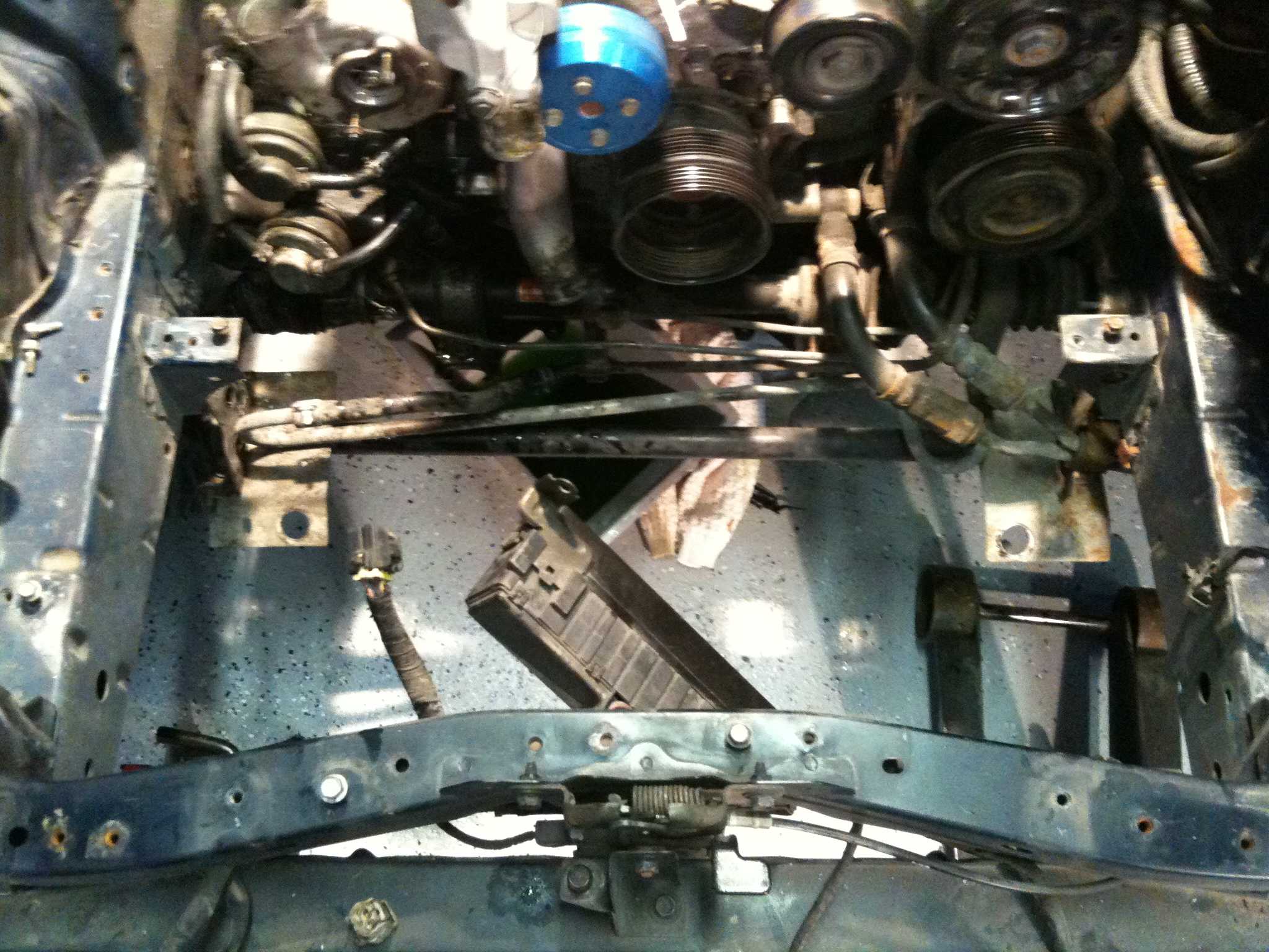
Underbody inspection matters in Australia. Sydney coastal salt and wet Melbourne winters encourage corroded terminals, while Perth heat and dust can mimic an intermittent open. Stone damage is common on country roads. The FC3S power-steering line routing is not a 13B-REW procedure, but it is a useful reminder to inspect adjacent lines, clips and loom paths after unrelated work rather than automatically blaming the CAS.
Also inspect the target or reluctor, sensor mounting and physical gap. Oil, coolant, debris or a distorted pickup can weaken the waveform without an obvious electrical break. Compare the pickup and trigger arrangement with the correct manual; FC, FD and 20B conversion hardware are not automatically interchangeable.
Confirm what the ECU receives
Once the waveform is sound at the sensor, verify it at the ECU. Probe the correct ECU terminal against ECU earth and compare the shape and stability with the connector reading. A waveform that collapses over the harness points to resistance, a chafed wire or a poor earth; a clean sensor-side trace with no ECU trace points elsewhere.
For 13B-REW data logging and setup, the 13B-REW PowerFC setup provides a useful reference for viewing live RPM and confirming that the ECU recognises the signal. Keep trigger and ignition configuration aligned with the actual CAS arrangement, and do not compensate for an unstable sensor with aggressive timing or fuelling changes.
A no-sync code does not identify the CAS by itself. Cam signal, battery supply, earth, target damage and ECU connectors can produce similar symptoms, so isolate the crank waveform before replacing parts.
Run the test in a repeatable order
Keep the diagnosis simple and save evidence. Use consistent probe points and record the waveform at idle, fast idle and cranking, with RPM and battery voltage written beside the trace. This makes an intermittent fault easier to catch and gives a specialist something more useful than a list of swapped parts.
- Download the correct factory manual and identify the CAS terminals before disconnecting anything.
- Rule out battery voltage, earth and connector problems before condemning the sensor.
- Measure the output at the sensor and ECU, comparing both traces under the same operating conditions.
- Record the waveform before changing trigger settings, ignition timing or fuelling.
Run the waveform check before ordering a sensor, save the trace with the vehicle’s service history, and use that evidence to guide the next electrical or mechanical step.